Download
1 / 37
370 likes | 486 Views
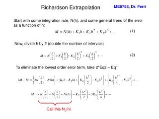
Comments about Extrapolation to LBN(E ) Barry Norris September 25, 2014. Outline. Overview of LBNE Design Showing the Layout of the Base Concept Outlining the Process System Strategy Concept of LN2 Flexibility to Support Future Detectors Identifying Items to Scale to LBN of Future.

E N D
Comments about Extrapolation to LBN(E) Barry Norris September 25, 2014 Barry Norris, Cryogenic Meeting at CERN September 2014
Outline Overview of LBNE Design Showing the Layout of the Base Concept Outlining the Process System Strategy Concept of LN2 Flexibility to Support Future Detectors Identifying Items to Scale to LBN of Future Barry Norris, Cryogenic Meeting at CERN September 2014
Comment The following represents the ideas and work of the LBNE Project. These slides don’t attempt to take into account any changes the future may hold for the direction we are headed as a community based in P5 recommendations. The LBNE Project has instructed cryogenic leadership (Norris, Montanari) to make the international partnership a priority and so we embrace a Collaborative effort and see this meeting as a launching pad for such a partnership. With that said, many of the ideas within the work of 35 ton and proposed LAr1-ND should lead to a future and successful LBNF facility once we succeed as a community in developing cryostat/cryogenic approaches that are valid for large detectors. Barry Norris, Cryogenic Meeting at CERN September 2014
Overview of Long BaselineNeutrino Experiment (LBNE) Cryostat Needs Aspects related to cryogenics: • The detector design is based on the use of membrane tank technologypreviously developed and used in commercial business for both storage and transport of liquefied natural gas (LNG). • The FD is planned to be initially composed of two membrane cryostats each having the approximate physical dimensions of 28.5 meters long, 15.6 meters wide and 16 meters high (7134 m3 volume). • Each cryostat will contain 9.4 kton (metric) LArmass. • The FD cryostat will house Time Projection Chambers (TPCs) used for particle detection and be filled with liquid argon filtered to less than 200 parts per trillion (ppt oxygen equivalent) contamination levels in order that electrons drift through the fluid with a lifetime greater than 1.4 ms. • In order to insure that membrane cryostat technology can be used within these requirements, Fermilab and the LBNE project have constructed and commissioned a prototype cryostat (~29 m3) referred to as the ‘35 Ton’, testing the thermal performance and the ability to achieve high purity levels. Barry Norris, Cryogenic Meeting at CERN September 2014
SURF Current & Future Science Program Barry Norris, Cryogenic Meeting at CERN September 2014
Plan View– Far Site Basic idea: Two 5-kt detector modules in one cavern and two 12-kt detector modules in a second cavern Barry Norris, Cryogenic Meeting at CERN September 2014
PFD for LBNE Far Detector Note: We view this cryogenic process essentially just a large version of same concept for 35 ton and Lar1ND approach Question for Us: What can be scaled up and what has to be completely different? LAr, GAr Supply GAr filtration Cryostat with Liquid Pumps Mole Sieve & Copper Filtration Re-condensor with LN2 Refrigeration 2 5 1 4 3 Barry Norris, Cryogenic Meeting at CERN September 2014
3-D Drawing of Underground Cavern Area for LN2 and LAr Refrigeration Systems Located here are LN2 coldboxes and LN2 storage Barry Norris, Cryogenic Meeting at CERN September 2014
3-D Drawing Cryostat North (N) Cryostat South (S) LAr filtration system in septum region Roof with trusses Roof with trusses APAs & CPAs Barry Norris, Cryogenic Meeting at CERN September 2014
LAr pump (GTT tank) This is strategy in our present design but is it the right one? Should we use external pumping? Does this issue scale with size? Removable pump at the bottom of the vessel Barry Norris, Cryogenic Meeting at CERN September 2014
Opening Assumption for 4850Cryogenic System’s Design Our cryogenic systems design strategy must take into consideration that the long range goal for the LBNE endeavor is to provide refrigeration capabilities for 34 kton fiducial mass detector arrangement (assuming ~ 50 kton total mass) whereas the initial minimum cryogenic system investment must support a 5 kton fiducial detector and probably two detectors for a 10 kton system (~ 19 kton mass). Barry Norris, Cryogenic Meeting at CERN September 2014
With the Opening Assumption in Mind… • We propose to design a centralized cryogenic facility where the GN2 compressors are on the surface and cold boxes are in cavern(s) supporting both 10 and 24 ktondetectors (fiducial mass). Note: Refrigeration cycle has been approximated based on heat loads for the LBNE Membrane cryostat design. • Propose to provide ‘Plug & Play’concept where future required cooling capacity is accomplished by adding warm compressor(s) and cold box(es) as needed to an already existing piping infrastructure. • All necessary CF infrastructure in place for full scale implementation • All piping installed from surface to cavern for full scale implementation • All power and cooling requirements installed for full scale implementation • Propose to have LN2 system work like a utility for future Users (detectors) such that a distributed piping system will be installed to deliver to future detectors the cooling needed. • Primary equipment located in 10 kton cavern (cold boxes, dewars) • Transfer line and piping will connect to 24 kton cavern from central area • May need small LN2 or LArdewar(s) in 24 kton cavern depending on experiment • Each future detector will potentially have its own strategies for argon condensing and filtration/purification, offering flexibility in future detector designs. However, the base infrastructure for LN2 and connecting piping will be in place for 34 kton support and it is my personal opinion that the field of cryogenic engineering for liquid argon detectors will greatly benefit from the joint development of systems used in this work. Barry Norris, Cryogenic Meeting at CERN September 2014
Basic Idea: Shown is MinimumInfrastructure for 9.8 metric tontotal mass@ 4850’ level (depth of 1.6 km) • Each refrigerator is 85 kW total cooling power • Entire infrastructure (piping, electrical power, water cooling, civil ) put in place to support future use of four 85 kW cooling power LN2 plants, which is the capacity required for 34 kton. • Idea is to make future expansion a type of ‘Plug & Play’ for compressors and cold boxes to create large distributed system and minimize the cost for design labor and installation. Initial installation: Two Cold boxes & two compressors for 9.8 kton ‘CRYO-1’ represents first 9.8-kton detector Barry Norris, Cryogenic Meeting at CERN September 2014
Example of Cooling Power Requirements for Two 9.8 kton Cryostats Barry Norris, Cryogenic Meeting at CERN September 2014
Future Expansion up to 34 kton Fiducial Mass • To increase capacity we need to add Compressors and cold boxes • Piping, electrical power, water cooling, civil required to support this expansion from day 1. • Assume CRYO-1 through CRYO-2 are 9.8 ktoneach • Assume CRYO-3 and CRYO-4 is any combination up to 24 kton total Barry Norris, Cryogenic Meeting at CERN September 2014
Exploring LN2 Plant Options Example of Collobaorative Knowledge Base: The LBNE Design would benefit greatly from previous knowledge gained in LN2 refrigeration used in other projects such as ATLAS • We have very preliminarily explored options both in the USA and internationally (including the solution used by ICARUS, Sterling Engineering) for LN2 a refrigeration plant • For this presentation we offer one solution from the company Cosmodyne, LLC. • Cosmodyne, LLC. sells a commercial product line which is suitable for our forecasted cooling power needs. They are even willing to re-package their standard unit to meet our spatial conditions as well as maximum weight considerations via the Ross shaft. • In the long-term, there will be a Request for Proposal (RFP) process and this package will be bid. • A Procurement strategy of ‘future cold boxes and compressors’ will need to be discussed should the Cryogenic plant be built in this ‘Plug & Play’ style. • Any intereted vendor of cryogenic equipment will need to meet LN2 cycle parameters as well as space and utility constraints Barry Norris, Cryogenic Meeting at CERN September 2014
Standard units range from 15 – 189 kW cooling power ELM Family can be purchased and even re-designed or re-packaged to meet our cooling and physical space needs Barry Norris, Cryogenic Meeting at CERN September 2014
Representation of Future Physical Arrangement Surface Ross Shaft Cavern E-Panel These pipes will support four 85 kW units Compressor After Cooler Expanders Coldbox Barry Norris, Cryogenic Meeting at CERN September 2014
But What Systems Would Scale from SBN or Other Work to LBNE Design? • Membrane Cryostat Technology • Design, Procurement, Construction Issues • We must learn from 35 ton to WA105 to LAr1ND to SBN-FD • This is great opportunity for LBN Program • Gas Purification • Liquid Filtration • We view this as Molesieve and Copper with automated regeneration • Need to understand best filter ‘material’ • Need to establish automated function (test bed) • Liquid Pumps • Internal pumps or External Pumps • Purity, Purity, Purity • Concepts for 100K Value Engineering • If separating gas ullage in independent buffer is valid, does it scale to the LBNE size detector world? Barry Norris, Cryogenic Meeting at CERN September 2014
Value Engineering Approach of LBNE • Earlier in this meeting you have heard LBNE engineers speak of internal versus external pumps as well as an idea to keep all surfaces of internal to the cryostat < 100 K for purity reasons. • These two ideas came out of LBNE Value engineering concepts where in a controlled manner we identify areas where we need to evaluate/identify areas of engineering study and development which might make significant changes to the base design show here. Both of these ideas are examples of that. • LBNE Project office is supportive of the idea of using LBNE resources to assist with design and implementation of such concepts inside of detectors like LAr1-ND. Barry Norris, Cryogenic Meeting at CERN September 2014
Concluding Slide We look forward to working together in accomplishing the tasks before us in a Collaborative manner and believe that the proposed LBNE design will/would benefit greatly from immediate work of this community. Barry Norris, Cryogenic Meeting at CERN September 2014
Back Up Slides Barry Norris, Cryogenic Meeting at CERN September 2014
Impurity Profile T profile verified in LAPD. Will be verified in 35 ton prototype as well. Barry Norris, Cryogenic Meeting at CERN September 2014
HV Feedthrus TPC Electrical feedthrus Laser calibration ports Electronic Racks Trusses TPC Electrical feedthrus HV Feedthru Service ports Laser calibration ports Barry Norris, Cryogenic Meeting at CERN September 2014
Primary Membrane Design Requirements (from RFP) Barry Norris, Cryogenic Meeting at CERN September 2014
Insulation Design Requirements (from RFP) Barry Norris, Cryogenic Meeting at CERN September 2014
Concrete and Vapor Barrier Design Requirements (from RFP) Barry Norris, Cryogenic Meeting at CERN September 2014
Cryostat Roof Design Requirements (from RFP) Barry Norris, Cryogenic Meeting at CERN September 2014
3 D Model for 10-kton Velocity & Temperature Profile T profile verified in LAPD and 35 ton prototype Barry Norris, Cryogenic Meeting at CERN September 2014
List of Penetrations through the Roof of each cryostat • 1 Access Hatch • 1 Personnel Hatch (1.2 m x 1.8 m nominal) • 20 TPC Electrical feedthru ports • Laser calibration ports (4” OD tube on 6” OD CF) • Service ports (LAr pumps, LAr/GAr inlet, GAr purge inlet/outlet, LAr cool down, PSVs, VSVs, LAr/GAr return, spares). • 30 lug style anchor points to hang TPCs • 3 HV feedthru ports (6” OD tube on 8” OD CF) Barry Norris, Cryogenic Meeting at CERN September 2014
Timeline for 35 ton Phase I Commissioning/Operations Barry Norris, Cryogenic Meeting at CERN September 2014
LBNE-FD Cryostat RFP Schedule Barry Norris, Cryogenic Meeting at CERN September 2014
LBNE-FD Cryostat Schedule Barry Norris, Cryogenic Meeting at CERN September 2014
Figure 2. Membrane cryostat construction photos: (a) Membrane cryostat section, reprinted from IHI Corporation; (b) Membrane panel in angle with screw; (c) Inside of the tank after completion; (d) Membrane panel in corner with screw; (e) Three-way anchor; (f) One-way anchor, and (g) Flat membrane panel screw Barry Norris, Cryogenic Meeting at CERN September 2014
Anchors David Montanari Barry Norris, Cryogenic Meeting at CERN September 2014