Download
1 / 8
80 likes | 225 Views
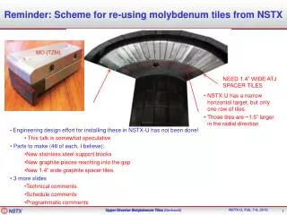
Reminder: Scheme for re-using molybdenum tiles from NSTX. NEED 1.4” WIDE ATJ SPACER TILES. NSTX-U has a narrow horizontal target, but only one row of tiles. Those tiles are ~1.5” larger in the radial direction. Engineering design effort for installing these in NSTX-U has not been done!

E N D
Reminder: Scheme for re-using molybdenum tiles from NSTX NEED 1.4” WIDE ATJ SPACER TILES NSTX-U has a narrow horizontal target, but only one row of tiles. Those tiles are ~1.5” larger in the radial direction. • Engineering design effort for installing these in NSTX-U has not been done! • This talk is somewhat speculative • Parts to make (48 of each, I believe): • New stainless steel support blocks • New graphite pieces reaching into the gap • New 1.4” wide graphite spacer tiles. • 3 more slides • Technical comments • Schedule comments • Programmatic comments
Suitability of tiles for NSTX-U? • Based on FDR presentation, conversations with Rick Woods: • Heat loads: • 1” thick molybdenum apparently used because the stock could be found. • Limit was a low-cycle fatigue limit for stresses above 300 MPa • Keep below 2 MW/m2, and beneath ~1200 C anywhere in the tile, all is (apparently) fine. • Designs with more complicated fasteners, 10 mm thick plate, had even better thermal properties. • Disruption loads: • Disruption loads were not a big problem for the design. • Possible that they could even take the full 2 MA, 1T loads, and almost certain that they could take the 1st year parameters. • Ned to revisit both analysis points, but neither appears to be a complete shot-stopper. • Must have a way of depositing low-Z coatings on molybdenum surfaces. • Development is underway for upward LITERs. • Can we assume they will be ready for routine use starting with the first plasma? • Boronization system has been removed from NSTX • B. Blanchard has expressed concern that it may need to be reconstituted with additional safety features compared previous. • Has been tasked with coming up with a design, schedule, cost estimates. • SPG Suggestion: must commit to a boronization system if going to use these tiles in the upper divertor.
There Remains Time to Implement This • Schedule for CSC • Casing shows up at PPPL in December 2012 • Probably start welding studs on in February 2013 • Install most tiles on CSC in late summer, early fall, 2013. • Horizontal target tiles are a special case…can’t be bolted down when the CS is lowered in. • Complete CS delivered to NTC in January 2014. • Case 1: Install horizontal diagnostic tiles on CSC in CTC. • Allows diagnostic feedthroughs to be connected in “comfort”, sensors checked easily. • Tiles would be “set aside” on the CS flange during installation • Tile installation time: ~September, October 2013 • Case 2: Install horizontal diagnostic tiles on CSC in NTC after installation in NSTX. • Organ-pipe diagnostic feedthroughs must be installed in the NTC. Life is difficult. • Tile installation time: ~February 2014 • Engineering has not decided on case 1 or 2 yet. • Schedule for molybdenum tile work (very approximate, and maybe optimistic given other potential personnel resource conflicts) • Design/analysis/drafting: 2.5 months • Fabrication of parts: 2 months • Disassembly/cleaning/assembly (provided the labor can be found): 2 months • Total: 6.5 months • Implications: • It will probably not be acceptable to delay CD-4 any meaningful amount for this project. • Probably need to make a decision in the late winter/early spring. • Should get a WAF started in the new year if we are seriously considering this.
Programmatic Comments • What would we learn: • How to, or if we can, coat bare molybdenum surfaces to avoid impurity problems. • LLD gives confidence that it is OK. • How much molybdenum the core plasma can tolerate. • How brave we need to be to implement a next step. • Primary reason to delay: • Don’t have impurity flushing schemes proven compatible with long-pulse, stationary operation. • Good chance we won’t have one until the cryo-pump is ready. • If ELM free with molybdenum influx, the shot will likely be very short. • Diagnostics: • “Required” very early in the operations campaign. • IR cameras on the upper divertors. • TC in the tiles. • Core spectroscopy that can detect molybdenum concentrations. • Main chamber bolometry. • Would a lack of these measurements early in the run impact our willingness to install tiles? • Desirable: Upper divertor spectroscopy. • “staged Mo conversion vs. wholesale conversion of upper and lower divertor” • Would be foolish to do a wholesale conversion w/o an initial test. • These tiles could provide such a test. • Recommendation: • These tiles may provide a low-cost means of “testing the water”, but their utility decreases as we move towards higher power and longer pulse operation. • Should be considered as part of a plan that provides for rapid follow-up with additional tiles. • Don’t do it earlier than necessary.
Other comments: • Need a plan soon…all the other chapters are waiting on this sequence. • High-Z coatings on tiles • High-Z coatings are a likely candidate for converting CS and PP tiles to high-Z. • Should consider coating select CS tiles, and select SPP tiles, to understand how well the coatings survive. • Do this in tandem w/ the molybdenum upper divertor • High-Z tiles and cryopump: • An additional expense associated with the cryo-pump will be reconstituting the bake-out system with new graphite tiles. • High-Z tiles likely do not need the full 350 bake, could use standard vessel bakeout temperatures (confirm this please…). • Should check cost implications of more expensive tile manufacturing vs. bake-out system reinstallation. • If sufficient confidence exists in use of high-Z tiles, then they could be installed as part of an “Advanced Divertor” w/ a cryo-pump. • NSTX-U was funded with graphite PFCs, Alcator C-Mod is at grave risk, despite molybdenum PFCs and plans for a hot W divertor. • We should plan the metal PFC program that we think is technically best.
Following Are Henry Kugel’s Slides at the Facilities Brainstorming Session (for your reference)
Replacing the Planned Upper Inner Divertor ATJ Tiles with Molybdenum Tiles Expands NSTX-U Capabilities • Installation of Molybdenum Tiles on the Upper Inner Divertor allows experiments to characterize: • Reduction of divertor carbon source term in USN discharges - measure effect on plasma core-carbon impurity accumulation • Comparison of power-handling during long-pulse DND discharge - measure upper and lower divertor heating and erosion • Prototype test for expanding molybdenum tile coverage - if performance enhanced, start engineering work for more Mo tile coverage • 3 AVAILABLE MoDIAGNOSTIC TILES- MAGNETIC SENSOR - THERMOCOUPLE - LANGMUIR PROBE • Remaining Tasks1. Perform fresh engineering analysis to determine NSTX-U, operating limits (Ip, Bt, NBI, rep). 2. Design and fabricate ATJ spacer tiles. 3. Resolve of diagnostic cabling issues. NSTX Mo TILE • NSTX-U CS RADIUS IS LARGER • NEED 1.4” WIDE ATJ SPACER TILES
Replacing Entire Upper Divertor ATJ Tiles with Molybdenum Tiles Accelerates NSTX-U Decision for All Metal PFCs • Number of NSTX ATJ tiles - Horiz Inr Div = 48 - Otr Div = 916 J.Menard Mo INR DIV TILE The outer divertor has 916, ATJ tiles, 1-inch thick arrayed in 5 tile styles (on 5 conic sections), fastened with Tee-bars to tapped holes in the copper baseplates containing heating/cooling pipes• could use inner divertor tile design for outer divertor, but 5 different tile styles required • a possible tile design consisting of a standardized geometry (e.g., cubes/CMOD) could reduce the number of tile styles and fabrication cost