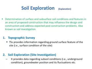
Soil Exploration ( E xplanation)
Soil Exploration ( E xplanation). Determination of surface and subsurface soil conditions and features in an area of proposed construction that may influence the design and construction and address expected post construction problems . Also known as soil investigation. Topographic Survey

Soil Exploration ( E xplanation)
E N D
Presentation Transcript
Soil Exploration(Explanation) • Determination of surface and subsurface soil conditions and features in an area of proposed construction that may influence the design and construction and address expected post construction problems. Also known as soil investigation. • Topographic Survey • TSs provides information regarding ground surface feature of the site (i.e., surface condition of the site) • Soil Exploration (Site Investigation) • It provides data regarding subsoil conditions (i.e., underground condition), groundwater position and its fluctuations etc.
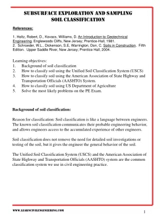
Purpose and Objectives of Soil Investigation The primary objective of the site investigation is as follows: • To assess the sequence, thickness and lateral extent of the soil strata and, where appropriate, the level of bedrock. • To obtain representative samples of the soils (and rock) for identification and classification to determine the relevant soil parameters. • To determine the position of GWT and limits of its fluctuation during wet/dry season. Thus exploration essentially provides information to decide about: i) The suitability of the site for proposed work ii) To develop economical design iii) To predict any construction problems along with their possible remedies.
Investigation Phases • Feasibility Phase (Reconnaissance): It generally involves collection of background information about the site. Following information is collected: • Project Details • Type of structure, intended use of structure, construction method, etc. • Surface and Subsurface Conditions of the site • Study of topographic/geologic maps, aerial photographs, data from previous investigations, satellite imagery, etc. • Study of existing structures in the area
Investigation Phases • Preliminary Investigation • Location of bedrock is established by drilling a few holes. Position of GWT may also be established. • Detailed Investigation • This phase may include test pits excavation, boreholes, in-situ testing and collection of both disturbed and undisturbed soil samples for detailed laboratory testing/analysis. GWT may also be monitored by installing piezometers. • Construction/Post Construction Investigation • Sometimes monitoring of movement of structure and monitoring of groundwater fluctuations, both during and after construction, may be required.
Amount of Exploration • By amount of exploration is meant to decide about the extent of investigation i.e., to determine the number, location, and depth of open excavations (pits, trenches, etc.) and borings/drillings. The extent of exploration depends upon many factors, major being the following: • Site condition (variability of soil/rock strata and GWT depth at site) • Nature and extent of the project. (building, highway, dam, etc.) • Availability of time, fund and equipment for exploration. • The main rule for determining the extent of investigations is that there is no hard and fast rule for this purpose.
Methods of Investigation • The methods to determine the sequence, thickness and lateral extent of the soil strata and, where appropriate the level of bedrock. The common methods include: • Test pits • Boring or drilling
1. Test Pits • The excavation of test pits is a simple and reliable method. • The maximum depth is limited to 4-5m only. • If the pit is to be extend below the GWT, some form of dewatering is necessary. • The in-situ conditions are examined visually. • It is easy to obtain disturbed and undisturbed samples. • Block samples can be cut by hand tools and tube samples can be taken from the bottom of the pit. • Test pits are suitable for investigations in all type of soil, including those containing cobbles or boulders.
1. Test Pits • Walls of the test pit indicate four layers (1) Clayey silt (2) Sandy silt (3) Clean sand (4) Sandy gravel
2. Boring or Drilling: • Boring refers to advancing a hole in the ground. • Boring is required for the following: • To obtain representative soil and rock samples for laboratory tests. • To identify the groundwater conditions. • Performance of in-situ tests to assess appropriate soil characteristics. • Some of the common types of boring are as follows: • Auger boring • Hand Augar • Mechanical Augar • Rotary drilling • Wash boring • Percussion boring
i. Augar Drilling 1. Hand Augar: • The hand augar (also called post-hole or Iwan augar) is a very simple hand tool used for drilling into soft soils down to maximum of 5-6m in small projects. • Hand-augered holes can be made up to about 20m depth, although depth greater than about 8-10m is usually not practical. • For hard soil and soil containing gravels boring with hand auger becomes difficult. • The auger is rotated until it is full of soil, then it is withdrawn to remove the soil and the soil type present at various depths is noted. • They can be used for soil exploration work for highways and small structures. • The soil samples collected in this manner are disturbed but they can be used for classification test in laboratory such as grain-size determination and Atterberg limits. • Auger boring may not be possible in very soft clay or coarse sand because the hole tends to collapse when auger is removed.
a Continuous Flight Auger Hand Augar Plugged while advancing the auger Plug removed and sampler attached Truck mounted auger boring machine
i. Augar Drilling 2. Mechanical Augar: • Mechanical Auger means power operated augers. The power required to rotate the auger depends on the type and size of auger and the type of soil. • Downwards pressure can be applied hydraulically, mechanically or by dead weight. • The diameter of the flight auger usually is between 75 to 300mm, although diameters up to 1m and bucket augers up to 2m are available. • Borehole depths up to 50m are possible with continuous-flight augers. • The most common method is to use continuous flight augers. Continuous flight augers can be solid stem or hollow stem with internal diameter of 75-150mm. • Hollow stem augers are used when undisturbed samples are required. Plug is withdrawn and sampler is lowered down and driven in to the soil below the auger. • If bed rock is reached drilling can also take place through the hollow stem. • The presence of cobbles and boulders create problems with small-sized augers. • There is a possibility that different soil types may become mixed as they rise to the surface and it may be difficult to determine the depths of changes of strata. Experienced driller can however detect the change of strata by the change of speed and the sound of drilling.
ii. Rotary Drilling • Although primarily intended for investigations in rock, the method is also used in soils. • Rotary drilling is a procedure by which rapidly rotating drilling bits attached to the bottom of drilling rods cut and grind the soil and advance the borehole down. • Water or drilling fluid is pumped down the hollow rods and passes under pressure through narrow holes in the bit or barrel: this is the same principle as used in wash boring.
Various types of diamond drill bits for rotary drilling Rotary Drilling
ii. Rotary Drilling • There are two forms of rotary drilling, open-hole drilling and core drilling. • Open-hole drilling, which is generally used in soils and weak rock, uses a cutting bit to break down all the material within the diameter of the hole. Open-hole drilling can thus be used only as a means of advancing the hole: the drilling rods can then be removed to allow tube samples to be taken or in-situ tests to be carried out. • In core drilling, which is used in rocks and hard clays, the diamond bit cuts an annular hole in the material and an intact core enters the barrel, to be removed as a sample. However, the natural water content of the material is liable to be increased due to contact with the drilling fluid.
iii. Wash Boring • Wash boring is another method of advancing a borehole. • In this method, a casing about 2m to 3m (6 to 10 ft) long is driven into the ground. • The soil inside the casing is then removed by means of a chopping bit that is attached to a drilling rod. • Water is forced through a drilling rod, and it goes out at a very high velocity through the holes at the bottom of the chopping bit. • The water and the chopped soil particles rise upward in the drill hole and overflow at the top of the casing through a T-connection. • The wash water is then collected in a container.
iv. Percussion Drilling • Percussion drilling is an alternative method of advancing a borehole, particularly through hard soil and rock. • The boring rig consists of a derrick, a power unit and a winch carrying a light steel cable which passes through a pulley on top of the derrick. • In this technique, the borehole is advanced by the percussive action of the tool which is alternately raised and dropped (usually over a distance of 1–2m) by means of the winch unit. • Borehole diameters can range from 150 to 300mm. The maximum borehole depth is generally between 50 and 60m.
Standard Penetration Test (SPT) • This test gives information about soil strength. • It is carried out at regular intervals during a boring operation or where change of strata is noted. • A split-spoon sampler is attached to the drill rods, lowered to the bottom of boreholes and driven into the ground by repeated blows of a standard 65kg hammer falling freely through 75cm. • The number of blows requires to drive the sampler through three consecutive depths of 15cm (total 45cm) are noted. • The SPT N value is the number of blows required to drive the sampler through the last 30cm. • If, for N > 50, the sampler penetrates less than 2.5cm, refusal is said to have been reached and the test is discontinued until the boring advances to a new depth.
Standard Penetration Test (SPT) • The standard penetration test is very useful for cohesionless soils and medium clays. • For gravels and stiff clays the results are not reliable. • The SPT test is very popular all over the world. It is simple, not too expensive, reliable, and generally repeatable. • It is extensively used in problems such as design of foundations, settlement analysis and liquefaction studies. • Among the sources of error are that: • The hammer should freely and through the correct distance • The sampler should be held vertically • The drill rods longer than 15m are likely to whip.
Cone Penetration Test (CPT) • This test provides a continuous record of resistance offered by a soil to a cone pushed into it. • The cone usually has a vertex angle of 60 and a base diameter of 50mm, but cones of different dimensions are also used. • It is attached to the end of the drill rod and pushed into the borehole by means of jack. • The resistance offered and the corresponding depth are recorded. This called a static cone penetration test. • In dynamic cone penetration test (DCPT) the cone is driven by the blows of a 65kg hammer (the same as in the SPT). • The number of blows required to drive the cone 30cm into the ground is noted. • The CPT is a useful test for gravel and coarse sand formations, especially below water table. • A CPT test is best used to corroborate the results of SPT or other test.
Soil Sampling • A sample is said to be representative sample when it truly represents the characteristics of the stratum from which it is recovered. • Disturbed Sample: • A disturbed sample is one having the same particle size distribution as the in-situ soil but in which natural moisture content is disturbed and soil structure has been significantly damaged or completely destroyed. • Disturbed samples, which are used mainly for soil classification tests, visual classification and compaction tests, can be excavated from trial pits.
Soil Sampling • Undisturbed Sample: • Undisturbed samples are obtained by techniques which aim at preserving the in-situ structure and water content of the soil. • It is impossible to obtain a sample that is completely undisturbed, no matter how elaborate or careful the ground investigation and sampling technique might be. • Undisturbed samples are used to determine the shear strength, compressibility and permeability of the materials. • All samples should be clearly labelled to show the project name, date, location, borehole number, depth and method of sampling. • Special care is required in the handling, transportation and storage of samples prior to testing.
Common Sampling Techniques: • Sampling by Standard Split Spoon • When the borehole is advanced to a desired depth, the drilling tools are removed. The split-spoon sampler is attached to the drilling rod and then lowered to the bottom of the borehole. The sampler is driven into the soil at the bottom of the borehole by means of hammer blows. The hammer blows occur at top of the drilling rod. The hammer weighs 63.5kg (140lb). For each blow, hammer drops a distance of 30in (.76m). The number of blows required for the driving the sampler through three 6in interval is recorded. The sum of the number of blows required for driving the last two 6in interval is referred to as the Standard Penetration Number, N. It is commonly called the blow count. The interpretation of the standard penetration number is given in the following table.
Common Sampling Techniques: • Sampling by Thin Wall Tube • It is used for obtaining fairly undisturbed soil samples. The thin wall tubes are made of seamless thin tubes and are commonly referred to as Shelby Tubes. The sampler is attached to the drilling rod and then lowered to the bottom of the borehole. After this, it is hydraulically pushed into the soil. It is then spun to shear off the base and is pulled out. The sampler with the soil inside is sealed and taken to the laboratory for testing. Most commonly used thin wall tube samplers have outside diameter of 3in. • Sample Disturbance • The degree of disturbance of the sample collected by various method can be expressed by a term called the area ratio, which is given by Ar = (Do2 – Di2) / Di2 where Di and Do are inside and outside diameter of sampler respectively.