Download
1 / 10
120 likes | 429 Views
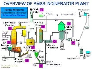
OVERVIEW OF PMSB INCINERATOR PLANT. Stack Outlet. Cooling Tower. Secondary Chamber. Fabric Filter. ID Fan. Rotary Contactor. Burners. Heat Exchanger. Process. Primary Chamber. Lime & Carbon Feeder.

E N D
OVERVIEW OF PMSB INCINERATOR PLANT • Stack Outlet • Cooling Tower • Secondary Chamber • Fabric Filter • ID Fan • Rotary Contactor • Burners • Heat Exchanger Process • Primary Chamber • Lime & Carbon Feeder
The 3 hydraulically operated rams slowly pushed ash through PC depositing ash on the burnout hearth Gaseous product from incomplete combustion discharged from PC are passed into ignition chamber. Primary chamber BACK DOOR ASH PUSHER WASTE BURNED INTO ASH
Secondary chamber • Pyrolised gases produced are mixed with excess oxygen and completely combusted with temperature of 1100°C in the secondary chamber. • The min. residence time in secondary chamber is 2 seconds. • The exhaust gases at 1100°C will pass into a heat exchanger and adiabatic gas quench, which reduces the temperature.
Downpass HE needed to provide preheated combustion air Ceramic tubed HE : to provide hot air for exhaust gas reheat whilst cooling the exhaust gas stream It cannot be let to thermal shock and must clean the HE using compressed air lance through access doors Heat Exchanger CERAMIC TUBE
Its function is to cool the exhaust gases to a acceptable temperature for entry to FF The exhaust gases are contacted with finely atomized water droplets Nozzle use compressed air to ensure the cooling water is finely atomized where liquid evaporated upon contact with hot gases Cooling Tower
Rotary Contactor • Lime and carbon contacted quencher outlet gas in rotary contactor • Hydrated lime and activated carbon pneumatically injected into drum • Fine particle entrained with gas stream whilst the larger one will retain within ball mill • Lime and carbon also help to neutralized the gases and trapped larger particles
Fabric Filter • Also called ‘stoking’ because its function is to trapped any larger particle before gas emission to open space • Reactants injected into FF and foam coating in all surfaces • Additional contact of exhaust gases through reactants completes the neutralization process • Cold spots always occur on the FF casing FILTER BAG
Induced Draft Fan • Provide the energy necessary to overcome the considerable resistance to gas flow in APC Plant • It is like ‘heart’ to APC Plant • Equipped with vibration sensor to detect any excess vibration
Exhaust Stack • Cleaned incinerator exhaust gases discharged from APC plant through stack at height 20 m above ground level • Equipped with test ports and access platform to permit emission testing
Burners • The incinerator is equipped with a PC ignition burner and 2 SC dual fuel burners • PC burner ignites the waste material • SC burners maintain desired temperature to burn the pyrolised gas • Other parameters i.e O2, CO and CO2 must be monitored to the combustion efficiency BURNERS BURNER AIR FAN