Download
1 / 15
150 likes | 225 Views
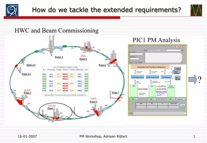
How do we tackle the extended requirements?. HWC and Beam Commissioning. PIC1 PM Analysis. ?. Extending the PMA system. Outline. Simple PM system dataflow view Known systems with PM requirements Three step PM analysis Software trigger Linking requirements, source code and results

E N D
How do we tackle the extended requirements? HWC and Beam Commissioning PIC1 PM Analysis ? PM Workshop, Adriaan Rijllart
Extending the PMA system Outline Simple PM system dataflow view Known systems with PM requirements Three step PM analysis Software trigger Linking requirements, source code and results Implementation extensions Recapitulation PM Workshop, Adriaan Rijllart
PM system dataflow view, one-step analysis Starting point in 2005 PM viewer Data bases PM server Result data Alarms PM analyser Logging Raw data files QPS PC PIC Other systems Systems … LHC PM Workshop, Adriaan Rijllart
Summary of systems with PM requirements Analyses well advanced Legend: y - produces data n - no data ? - not know yet But all need PMA! PM Workshop, Adriaan Rijllart
PM data flow, two-step analysis PM system, evolution during 2006 SDDS Result 1 Result 2 HWC viewer QPS-PMA QPS viewer PC-PMA second analysis PC viewer PIC-PMA PIC viewer Clear advantage to introduce 2nd step analysis. Alarms Logging Meas. Data bases PM Workshop, Adriaan Rijllart
Trigger Circuit Equip Equip MS Equip Equip Vac PIC PC Circuit Equip Circuit Equip Cryo BLM QPS Architecture of PMA system, three-step including trigger Raw data Analysis trigger Individual system analysis Result data 1 Logical system analysis Result data 2 Logical system conclusion SDDS logging Logical system conclusion Magnet system Cryo circuits DFB SCLink Stand. cell additional results
Trigger X1 BPM Equip Equip RF PC Cryo BIC Circuit BLM XPOC Circuit X3 X2 Equip Circuit BS MS Equip Equip Vac QPS PIC Equip Y1 Architecture of PMA, extended to beam data analysis Individual system analysis Logical system analysis Logical system conclusion SDDS logging Magnet system Cryo circuits DFB SCLink Stand. cell Direction of extension Beam systems
Trigger PC PIC Vac BLM QPS Cryo Why a trigger module? Raw data Analysis trigger Individual system analysis Reasons: SDDS • Individual System analysis modules dealing with logging data need to know when to start • Individual System analysis modules dealing with SDDS data could detect when to start by itself or rely on the trigger module • Logical system analysis modules combining logging and SDDS data need trigger module or would need to communicate with Individual System modules • Manual triggers could be given by an operator through the trigger module • If all analysis modules rely on the trigger module this can also fulfill the task of monitoring the analysis process logging PM Workshop, Adriaan Rijllart
PMA Software trigger PMA Trigger Summary Config System Activity System flag Analysis Result Domain PC messages User level QPS 09:12:04.255 PC error 09:12:04.360 BLM threshold crossing Views PIC CRYO VAC BLM BPM XPOC PM Workshop, Adriaan Rijllart
Manual trigger Logged signal P arbritrary units analysis interval Alarm PM trigger time Manual trigger PM Workshop, Adriaan Rijllart
Linking requirements, source code, docs and results PMA_home QPS Excel file QPS_req1.1 QPS_prog1.1 QPS_doc1.1 QPS_res1.1 Word file PC PC_req1.1 PC_req1.2 PC_prog1.1 PC_prog1.2 PC_doc1.1 LabVIEW source PC_doc1.2 PC_res1.1 PC_res1.2 Program_description.doc Text, XML or DB transfer PM Workshop, Adriaan Rijllart
Different ways to implement mathematical analysis There are at least 4 ways to implement mathematical analysis in LabVIEW LabVIEW diagram Formula node MATLAB script C code in LabVIEW clear all kr = 1*1; ki = 1*1; phi = 1*pi/4; xmax = 15; xmin = -4; delx = 0.1; x = [ 0:delx:xmax]; x2 = [xmin:delx:xmax]; #include <gd.h> #include <gdfontg.h> #include <gdfontl.h> static int red = 0; static int green = 0; static int blue = 0; void setupcolor(char *str); int main(int argc, char *argv[]) { FILE *pngout = {0}; gdImagePtr img; int fgcol, bgcol; char *str = NULL; PM Workshop, Adriaan Rijllart
LabVIEW mathematical analysis libraries Main palette 600 available functions PM Workshop, Adriaan Rijllart
Does LabVIEW analysis scale? • LabVIEW compiled code compares to C for memory use and speed • However the Graphical User Interface (GUI) can slow down the execution, but sub program blocks don’t need to show their GUI • For tracing and debugging purposes all sub programs can show their GUI on user request • LabVIEW code can run entirely without GUI using the technique of virtual display, for execution on a head-less linux server • Tests should be done how many QPS or PIC modules we can run on one computer before a slowdown is noticed PM Workshop, Adriaan Rijllart
Recap of «How do we tackle the extended requirements » Three-step analysis gives best data reduction and processing for the problems to be solved Software trigger module gives flexibility for automatic and manual triggering Extension to beam related equipment has been shown Linking documentation of requirements (xls, doc) to source code, to code description and to results using a reference system Analysis implementation can integrate LabVIEW diagrams, formula nodes, MATLAB scripts and C code A scaling test, running many analysis modules in parallel, needs to be done to determine what is the limit of one computer PM Workshop, Adriaan Rijllart