Download
1 / 22
250 likes | 599 Views
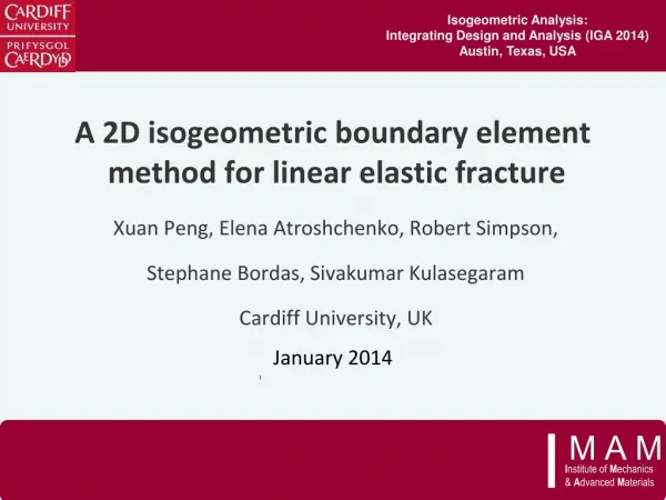
Isogeometric Analysis: Integrating Design and Analysis (IGA 2014) Austin, Texas, USA. A 2D isogeometric boundary element method for linear elastic fracture. Xuan Peng , Elena Atroshchenko , Robert Simpson, Stephane Bordas , Sivakumar Kulasegaram Cardiff University, UK. January 2014.

E N D
Isogeometric Analysis: Integrating Design and Analysis (IGA 2014) Austin, Texas, USA A 2D isogeometric boundary element method for linear elastic fracture XuanPeng, Elena Atroshchenko, Robert Simpson, StephaneBordas, SivakumarKulasegaram Cardiff University, UK January 2014 1
Outline 1/21 • Motivations • Modeling strategy by IGABEM • Numerical examples
2/21 Motivation • Goal • develop a robust, efficient and accurate program system for 3D fracture simulation and fatigue life prediction based on isogeometric boundary element method (IGABEM)
Motivation 3/21 • Bordas&Moran (2006) • Mesh burden • Expensive computational cost
4/21 Motivation • BEM is suitable for modeling fracture problems Dimensional reduction Boundary mesh modification High accuracy • IGABEM shows more advantages keep the exact geometry Natural fit with BEM Release the mesh burden further Higher order continuity • Drawbacks of BEM • High complexity in assembling (O(N2)) and solving (O(N3)) • Full populated matrix • Awkward in non-homogeneous, non-linear material
Dual BEM for crack modeling 5/21 • Displacement BIE: non–crack boundary and one crack surface • Traction BIE: the other crack surface
NURBS discretisation and collocation 6/21 • GrevilleAbscissae: • NURBS(B-Spline) • p=2 • Discretised BIEs • DiscontinousLagange • p=2
Singular integration for source points on non-crack surfaces 7/21 • Rigid body motion:
Singular integration for source points on crack surfaces 8/21 • Singularity subtraction technique:
Evaluation of stress intensity factors 9/21 • Contour integral based methods: • M integral (involving J1): • J integral (involving J1 and J2): Singular in evaluatingJ2
Algorithm for crack propagation 10/21 • Space constraint , parametric constraint • Maximum hoop stress criterion • Localization constraint function • Calculate the moving vector
Numerical examples: Griffith crack 11/21 • NURBS(B-Spline) • p=2 Mode I: Mode II: • DiscontinousLagange • p=2 Uniform mesh refinement No special treatment for crack tip
Numerical examples: inclined centre crack 13/21 • IGABEM(r) :Uniform mesh (refined tip element) • LBEM: discontinuous Lagrange BEM • SGBEM: symmetric Galerkin BEM, Sutrahar&Paulino (2004) m: number of elements in uniform mesh along the crack surface
Numerical examples: inclined centre crack 14/21 • Investigation with varied angle:
Numerical examples: arc crack 15/21 • Uniform mesh + refined tip element • Splitting parameter in J integral:
Numerical examples: crack growth from rivet holes 16/21 • 12 elements for each circle • 3 elements for initial cracks with tip refinement
Numerical examples: crack growth in a spanner 17/21 • Simpson et al (2012) • Contour of Mises stress in elastostatic analysis
Numerical examples: crack growth in a spanner 19/21 • IGABEM • XFEM
References 20/21 • R N Simpson, S P A Bordas, J Trevelyan, and T Rabczuk. A two-dimensional IsogeometricBoundary Element Method for elastostatic analysis. Computer Methods in Applied Mechanics and Engineering, 209212(0):87100, 2012. • M A Scott, R N Simpson, J A Evans, S Lipton, S P A Bordas, T J R Hughes, and T W Sederberg. Isogeometric boundary element analysis using unstructured T-splines. Computer Methods in Applied Mechanics and Engineering, 254(0):197221, 2013. • A Portela, M H Aliabadi, and D P Rooke. The dual boundary element method: Effective implementation for crack problems. International Journal for Numerical Methods in Engineering, 33(6):12691287, 1992. • A Sutradhar and G H Paulino. Symmetric Galerkin boundary element computation of T-stress and stress intensity factors for mixed-mode cracks by the interaction integral method. Engineering Analysis with Boundary Elements, 8(11):13351350, 2004. • N Moës, J Dolbow, and T Belytschko. A Finite element method for crack growth without remeshing. International Journal for Numerical Methods in Engineering, 46(1):131150, 1999.
Future works 21/21 • Crack tip enrichment • 3D implementation Acknowledgements: Thanks given to the Framework Programme 7 Initial Training Network Funding under grant number 289361 "Integrating Numerical Simulation and Geometric Design Technology” (FP7: ITN-INSIST) Thanks for attention