Download
1 / 4

E N D
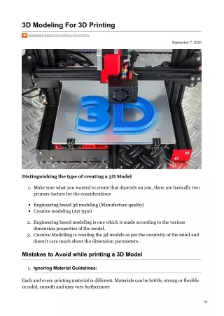
3D Modeling For 3D Printing makenica.com/3d-modeling-3d-printing September 7, 2020 Distinguishing the type of creating a 3D Model 1. Make sure what you wanted to create that depends on you, there are basically two primary factors for the considerations Engineering based 3d modeling (Manufacture quality) Creative modeling (Art type) 2. Engineering based modeling is one which is made according to the various dimension properties of the model. 3. Creative Modelling is creating the 3d models as per the creativity of the mind and doesn't care much about the dimension parameters. Mistakes to Avoid while printing a 3D Model 1. Ignoring Material Guidelines: Each and every printing material is different. Materials can be brittle, strong or flexible or solid, smooth and may vary furthermore 1/4
Solution: Follow the design rules of your material for a successful print. 2. Ignoring Wall Thickness: Wall thickness issues can be a major as to why the 3D models cannot be printed. In some cases, wall thickness is too thin and can be very fragile and could break off easily. Walls which are too thick generate too much internal stress and could cause the item to crack or even break. 3. Ignoring Printing Technology: The technologies that are used for printing each of these materials are different For ABS we use Fused Deposition Modeling (filament-based) with an extra nozzle and material for support, for Polyamide, Alumide, and Polypropylene we use Laser Sintering (powder-based), for precious metals we use lost wax and for the Resins we use Stereolithography (liquid polymer-based). 4. Ignoring File Resolution: The most common file format used is STL (standard triangle language), which means that your design will be translated into triangles in a 3D space. Most of the 3D modeling software has the option to export your designs to an STL file and set the desired resolution. Low-resolution STL file: It’s important to be aware that a poor-quality export will never lead to a good print. It will lead to “pixelated” print. Very high-resolution STL file: A high resolution file may make it difficult to handle. Solution: You will be asked to define the STL tolerance while using the software. This is defined as the maximum distance between the original shape and the STL mesh you are exporting. 5. Ignoring Software Guidelines: Even if you use a beginner-friendly software that was developed for the sole purpose of 3D Printing services you might still have a difficult time creating a hollow model. If you use a software used for 3D graphics and animations or software SketchUp used by architects and scale modelers, some further file preparation will need to be done. You may need to make models watertight, set the shells and even mark wall thickness based on your software. Once again, each and every software is different. Also Read : The Vast Variety of 3D Printing Materials- A Simple Guide 3D Printing Technology Types for 3D Modelling 2/4
We’ll take a look at the most common manufacturing complications of FDM, SLA, and SLS and how to address them when a model is in the design phase. Fused deposition modeling (FDM) is by far the most popular process of 3D printing. FDM printers are also the lowest-priced. What needs to be considered when designing for FDM? Build Plate Adhesion: A model should ideally have a large, flat side that can be oriented downward. This will provide enough surface area to sufficiently adhere to the build plate as the first layer is printed. Supported Parts: FDM printers extrude from the build plate up, so a model shouldn’t have any parts that are disconnected from the main body or any unsupported surfaces above the build plate. You can’t print in thin air with any 3D printing process, so make sure to design each part so that it can contact the build surface. Overhangs: While modeling, best practice is to have overhangs supported on both sides or to use angles of less than 45 to 60 degrees to the vertical (depending on your printer’s capabilities). Accuracy & Deformation: Horizontally-oriented holes of medium to smaller sizes are often deformed during the FDM printing process. Furthermore, supports can’t easily be removed from small or deep holes, so it’s recommended to keep them large or oval- shaped to account for shrinking and deformation. Another option is to purposefully design them to be small and later enlarge them with a drill Infill: With FDM printing, parts that are modeled solid have the option in the slicer software to be printed with a patterned, mostly hollow internal geometric structure, rather than being solid material. Material: When designing, it’s good to think about the eventual material, especially regarding its strengths and weaknesses. For instance, ABS is strong and heat-resistant but warps easily while printing. Therefore, for a wider part, a similar material like PETG or Nylon may be a better choice. Stereolithography (SLA) typically uses a bath of resin, from which layers are selectively solidified by a laser to form a finished model. Drainage: A popular technique is to design a model to be hollow and include drainage holes. When doing this, make sure to place holes in enough places to allow the resin to be easily drained, without marring the final appearance of your model. Surface Area & Supports: When it comes to design, the best way to avoid this is to ensure your print has a wide enough base. This will increase the surface area resting on the build plate, and this extra adherence will better cope with delamination forces. Detail & Deformation: Unlike FDM, SLA is able to produce very detailed models. 3/4
Despite their fragility and longer print times, the result is typically superior in resolution and precision. For this reason, designers have the opportunity to create features that aren’t possible with FDM. This includes small-sized holes, threads, interlocking parts, complex textures, and fine details. Trapped & Residual Resin: To entirely avoid interlocking parts, and print separate components to be assembled later. In the case that this is not possible or desirable, the alternative is to provide access for the resin to drain from these areas, or clearance to clean and dry the affected parts prior to curing. Material: When printing in SLA, there are fewer choices in resin compared to FDM. That said, enhanced performance materials do exist, like durable resin or castable resin. If you’re planning to use such a material, think about what sort of performance it will allow and design with these possibilities in mind. Selective laser sintering (SLS) shares properties with the SLA process. SLS uses a print area that’s entirely filled with material throughout the printing process, selectively solidifying a model in layers with a laser, similar to SLA. The main difference between SLS and SLA is that, while SLA uses liquid resin as the print material, SLS uses powdered plastic (or metal in higher-power machines). Unsupported Features: Due to the nature of SLS printing, the unsintered powder surrounding the model automatically supports the printed component, meaning no additional supports are required. Hollow Spaces: Similar to SLA, in SLS, any hollow spaces or complex internal infill structures within a part will naturally contain residual powder after printing. Since the powder is more difficult to remove than resin, it’s often better to redesign any hollow parts to be solid or incorporate easy interior access to remove the unsintered powder. Durability & Precision: If a model is planned to be printed with SLS, it can be designed more streamlined, lighter, and more aesthetically pleasing than the heavy, bulky, and boxy prints of the same strength from printing methods like FDM. Interlocking Parts: Print-in-place interlocking parts were mentioned as an issue in the SLA process, and there are similar issues with SLS. By nature, an interlocking joint needs a tolerance or gap between the mating parts. When all of the negative space is filled with powdered material, as it is in the SLS process, this can result in a rough or unmoving joint, as it will be filled with granules of material that need to be cleared out. 4/4