Download
1 / 33
330 likes | 471 Views
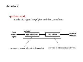
LBT672 current Adsec technology: Actuators / distribution boards Backplate coating / capacitive sensor Dust contamination Control system bandwidth Communication and control system performances. ACTUATORS PATTERN : MMT336 & LBT 672. BACK PLATE FEA. Mirror:.

E N D
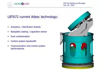
ESO AO Meeting at Microgate July 10th, 2002 • LBT672 current Adsec technology: • Actuators / distribution boards • Backplate coating / capacitive sensor • Dust contamination • Control system bandwidth • Communication and control system performances
ESO AO Meeting at Microgate July 10th, 2002 ACTUATORS PATTERN : MMT336 & LBT 672
ESO AO Meeting at Microgate July 10th, 2002
ESO AO Meeting at Microgate July 10th, 2002 BACK PLATE FEA Mirror: • front radius = 1974.24 mm • thickness = 1.5 mm Back plate: • DOUT = 911 mm DIN = 56 mm • DACT = 14 mm • front radius = 1975.74 mm • thickness = 50 mm • material ULE : E=6600x107 Pa r=2200 kg/mm2n=0.17 • mass = 56 Kg
ESO AO Meeting at Microgate July 10th, 2002 PTV RMS STD ZENITH 245 nm 219 nm 53 nm ELEVATION
ESO AO Meeting at Microgate July 10th, 2002 ADSEC + HEXAPOD MODAL ANALYSIS • first bending mode frequency at 33 Hz • piston mode at 73 Hz and the second bending at 91 Hz • three 15 Kg lumped masses included to model the electronics crates
ESO AO Meeting at Microgate July 10th, 2002 ADSEC + HEXAPOD STATIC ANALYSIS • horizon pointing load case displacement pattern: maximum displacements as function of the telescope elevation.
ESO AO Meeting at Microgate July 10th, 2002 ACTUATORS FRONTAL MOUNTING • maintainability • distribution boards (no cables) • improve capsens flexible contacts • better axial alignment on reference surface • dust shields
ESO AO Meeting at Microgate July 10th, 2002 ACTUATOR FEATURES • cold plate eccentric mount • better thermal contact • 90 deg turn key • axial adjustment • capsens contacts • higher position = magnets clearance • plug-in PCB • no cables • screwed bobbin • copper VS aluminum cold finger • maintainability
ESO AO Meeting at Microgate July 10th, 2002 MAGNET/ COIL ASSEMBLY • ZERODUR puck 6 x 2 mm • permanent magnet 11 x 3.6 mm • coil winded on a copper / aluminum frame • 6 mm core into the coil frame • copper thermal shielding hat • “remoted” capsens contacts
ESO AO Meeting at Microgate July 10th, 2002 EXTERNAL ACTUATOR • special capsens PCB • flat connector to distribution board • same coil as other actuators • lateral screwed mount
ESO AO Meeting at Microgate July 10th, 2002 DISTRIBUTION BOARDS
ESO AO Meeting at Microgate July 10th, 2002 DISTRIBUTION BOARDS (cntd)
ESO AO Meeting at Microgate July 10th, 2002 DISTRIBUTION BOARDS (cntd)
ESO AO Meeting at Microgate July 10th, 2002 ELECTRONICS CRATES • three crates (like two MMT336 ones in parallel) • 6 sub-crates x 18 control boards x 8 channels = 672 actuators • three heat exchangers on each crate = 9 cooling lines
ESO AO Meeting at Microgate July 10th, 2002
ESO AO Meeting at Microgate July 10th, 2002 CONTROL BOARD SLOT
ESO AO Meeting at Microgate July 10th, 2002 LBT672 POWER DISSIPATION ESTIMATE • Conditions • =0.55µm, r0=0.15m • Mirror flattening RMS force = 0.02 N @ t=1.6 • Coil efficiency: 0.5 N/W • Dynamic not considered !
ESO AO Meeting at Microgate July 10th, 2002 LBT672 COOLING SYSTEM • r0 = 0.15 m, = 0.55 mm • mirror thickness = 1.6 mm • mirror + magnets mass = 4.79 Kg • total actuator RMS force = 0.244 N • (seeing + weight + 0.02 N RMS for mirror flattening) • actuator efficiency =0.5 N/sqrt(Watt) • total power for each actuator = 239 mW + 90 mW (capsens) = 329 mW • coil to coldplate thermal impedance: 5.7 °K/W (aluminum actuator) • coil to mirror thermal impedance: 2 °K/W (aluminum actuator, TBC) • (Tamb-0.3) < Tmirror (Tamb+1.7) °C
ESO AO Meeting at Microgate July 10th, 2002 LBT672 COOLING SYSTEM (continued) • Coolant: 50/50 ethylene glycol and water solution:CP=3609 J/KgC k = 0.49 W/mCr = 1045 kg/m3 n= 1.84x10⁻³ Pa s • mirror thickness 1.8 mm • total crates power 3400 W • max TOUTLET-TINLET 2 °K • Total flow rate 28 lit/min
ESO AO Meeting at Microgate July 10th, 2002 CAPACITIVE SENSOR THERMAL STABILITY (Optical open loop operation) • Specifications: • 20nm RMS during one night T < 4°C • Stability performance has been tested on LBT P45 sensors: • the measurement has been taken with solid state capacitors instead of the actual probe, placed very close to each other. • temperature range: -20 to +40 °C • humidity not under control • This test does NOT take into account dielectric constant change due to humidity and temperature ! • Measured stability: • 0.35 nm/°C @ gap=gapnom (50µm)
ESO AO Meeting at Microgate July 10th, 2002 COOLING CHANNELS • channels cut from one side • sealed pipes (no gluing) • special external channels
ESO AO Meeting at Microgate July 10th, 2002 LBT672 POWER DISTRIBUTION • Implemented solution: DISTRIBUTED POWER SUPPLY • PROS • Just two, higher voltage supply rails (96V @ ~ 35A) – three cables ! • Power cables length practically not limited, remote sense not required • Takes advantage of growing communication technology • CONS • Slightly more complex system • Switching noise: • High frequency switching power bricks • Output filters
ESO AO Meeting at Microgate July 10th, 2002 LBT672 POWER DISTRIBUTION SCHEME
ESO AO Meeting at Microgate July 10th, 2002 LBT672 CONTROL SYSTEM • 6 crates, 14 DSP boards + 1 communication board each • 8 channels controlled by each DSP board, 4 DSPs/board • 112 channels/crate • DSP type: ADSP 21160, 180 Millions multiply and add operations per second, 32x32 = 40 bits floating point • Total computational power: 128 Gflops, 64 GMACs/s • Sensor bandwidth: increased form 26 KHz (MMT) to 90 KHz • Actuator current driver bandwidth: 56KHz, OK ! • Sensor noise: measured noise on LBT sensor at same level of MMT (~ 4nm RMS @ 50µm gap) • Computational delay
ESO AO Meeting at Microgate July 10th, 2002 COMMUNICATION on LBT672 • Adaptive secondary control system connected to the Slope computer by means of two fibers • Daisy chain concept (can be expanded) • DMA access to the whole memory of all DSPs • Efficient burst data transmission/reception
ESO AO Meeting at Microgate July 10th, 2002 COMMUNICATION: LBT672 (continued) • Two separated communication links available for real time data and diagnostic • Fast communication • Maintains the same daisy-chain concept of MMT • Interface: Fibre channel, operating at 2.125 Gbit/s. Two links available, for an aggregate bandwidth of 4.25 Gbit/s (3.4/2.25 Gbit/s of actual data bandwidth, without/with Forward Error Correction) • DSP internal memory is accessed via DMA processes, absolutely without any software overhead • Diagnostic • Standard 10,100,1000 Ethernet link over fiber • Used for diagnostic communication and system configuration (Ethernet link is always available after system booting) • Communication over a simple UDP/IP protocol
ESO AO Meeting at Microgate July 10th, 2002 LBT672 MIRROR CONTROL TIMING
ESO AO Meeting at Microgate July 10th, 2002 WHAT’S ALL THAT WASTED POWER ? RECONSTRUCTOR ! Computations to be performed by DSPs: all what comes after the slopes computation • + General IIR filter (gain matrixes are computed off-line on base of modal gains) • Feedforward • Local control loop • Diagnostic, data storing • Communication • Updated p need to be transferred among all DSPs Read_write_simultaneous
ESO AO Meeting at Microgate July 10th, 2002 RECONSTRUCTOR+CONTROL TIMING DIAGRAM
ESO AO Meeting at Microgate July 10th, 2002 LBT672 PERFORMANCE ESTIMATE (includes Slopes Computation by Microgate Basic Computational Unit) • Test conditions • Computational power contingency: 25 % • 672 actuators • 2 channels/DSP • 32x3240 bits floating point MACs
ESO AO Meeting at Microgate July 10th, 2002 LBT672 INTERFACES • Mechanical • Single interface flange to the alignment system • Cooling • Two manifolds: 28 l/min coolant flow, p ~ 1.5 bar @ 10°C (TBC) • Electrical • ± 48V @ 35 A (three cables) • 3 digital signals • Data • 62.5/125 µm fiber connection (2x TX + 2x RX), 2.125 Gbit/s each • 62.5/125 µm fiber connection (6x TX + 6x RX), 1.25 Gbit/s or 100 Mbit/s each, for Ethernet diagnostic connection
ESO AO Meeting at Microgate July 10th, 2002 LBT672 SCHEDULE • P45 engineering model • Fall 2002 electromechanical integration and testing (MMT electronics, new capacitive sensors and distribution boards) • Winter 2002/2003: LBT electronics testing • LBT672 #1 • electromechanical integration: Fall 2003 • Optical test in Arcetri: Winter 2003/2004 • LBT672 #2 • electromechanical integration: Winter 2003/2004 • Optical test in Arcetri: Spring 2004