Actuators
Actuators. Instructor: Shuvra Das Mechanical Engineering Dept. University of Detroit Mercy. Summary. Actuators Some actuator examples Switches Electric motors Piezo-actuators Mechanisms. Flowchart of Mechatronic Systems. Actuators. Elements that can execute physical action

Actuators
E N D
Presentation Transcript
Actuators Instructor: Shuvra DasMechanical Engineering Dept. University of Detroit Mercy
Summary • Actuators • Some actuator examples • Switches • Electric motors • Piezo-actuators • Mechanisms
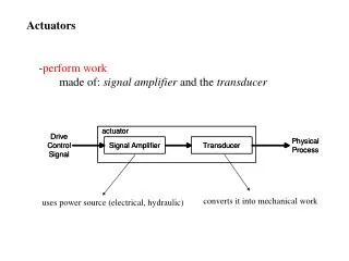
Actuators • Elements that can execute physical action • Electromechanical elements - receive input from controllers • Controller could be dedicated or embedded in software • Software control needs D/A signal conversion
Role of Actuators Electrical actuation signal (from controller) Actuator (pneumatic, hydraulic, motor, switch, etc.) Mechanical load Mechanisms (belts, pulleys, gear trains, etc.)
Actuators: Typical Actions • Move a load • Open a valve to increase flow • Rotate a shaft • …….
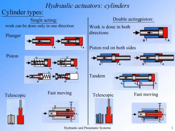
Actuators: Examples • Hydraulic or Pneumatic cylinders • Control valves • Electric motors • Switches • Relays • electric motors are most common actuators but for high power requirements Hydraulic or pneumatic ones are used.
Types of Actuators • Hydraulic Actuators • Mechanical Actuators • Electrical Actuators
Electrical Actuators • Switching devices: mechanical systems, relays or solid-state devices, control signal switches an electrical device on or off • Solenoid type devices: current through a coil activates an iron core that controls a hydraulic or pneumatic valve • Drive systems: D.C. and A.C. motors, where a current through a motor produces rotation
Electromagnetic Relays • A mechanical switch can be closed or opened as a result of control signal • When the coil is energized it pulls the plunger closing mechanical contact • Used in activating motors or heating elements • Demagnetization leads to contact loss • NO: normally (unenergized) open • NC: normally (unenergized) closed
Solenoid relays • Electrical Energy converted to linear mechanical motion • De-energized state: Plunger half-way inside the coil • Energized state: Plunger pulled in completely • e.g. car door locks, opening/closing valves • disadvantage: stroke very short
Solid State Relay • Input signal: typically 5V DC, 24V DC, or 120V AC • Input circuit works like EMR (electro-magnetic relay) • Output circuit works like EMR as well • output circuit can be AC and electronic switch capable of supporting large currents • LED and phototransistor pair optically coupled, i.e. light activates electrical signal in photo transistor
Solid State Relay • The amplifier boosts the signal to a suitable level to trigger the triac • Triac: electronic switch that supports current in both directions • Input => LED => phototransistor => amplifier=> triac => actuation output • Separates high power output side from low power input side
Disadvantages (elec.) False triggering through noise Failure unpredictable when on-not 100% short; when off -not 100% open Advantages(electronic) No contact-no wear No contact bounce No arcing Faster Maybe driven by low-voltage Electronic Vs. Mechanical Switches
DC Motors • Current carrying conductor in magnetic field experiences force (Lorentz effect) • A conductor moved in a magnetic field generates (back) emf that opposes the change that produces it. (Faraday/Lenz’s law) • Back emf rate of change of flux • Current due to back emf in closed circuit will create a flux opposite the magnetic flux • motor direction is reversed by reversing the polarity of voltage
DC Motors • Armature coil is free to rotate in the magnetic field • Loop of wire is connected through the commutator to the brushes (brushes stationary, commutator rotates) • Current flows when power is supplied to brushes
DC Motors • Opposite forces on opposite sides generates a torque • Commutator changes current direction when the plane of wire is vertical • Torque direction remains unchanged • Multiple wires are wound in a distributed fashion over cylindrical rotor of ferromagnetic material • Multiple loops increases and also evens out the torque
Permanent magnet DC Motors • Permanent magnet provides a constant value of flux density. • For an armature conductor of length L and carrying a current Ithe force resulting from a magnetic flux density B at right angles to the conductor is B IL.
Permanent magnet DC Motors • With N conductors the force is F=N B I L. The forces result in a torque about the coil axis of Fc, if c is the breadth of the coil, T= (NBLc)I . • Torque is thus written as T= KTI; I=armature current,KT is based on motor construction.
Permanent magnet DC Motors • Since the armature coil is rotating in a magnetic field, electromagnetic induction will occur and a back emf will be induced. The back emf E is related to the rate at which the flux linked by the coil changes. For a constant magnetic field, is proportional to the angular velocity of rotation. • Back emf is related to flux and angular rotation (in rpm) E= KEw; w= motor speed in rpm. • KT and KE depend on motor construction
R V E Permanent magnet DC Motors • The motor circuit can be represented as: • The current in the circuit is I= (V – E)/R
Permanent magnet DC Motors • Armature current, I= (V – E)/R.R is the armature resistance and E is back emf. • The Torque therefore is T= T= KTI = KT (V – E)/R = KT (V – KEw)/R • At start-up, back emf is minimum therefore I is maximum and Torque is maximum. The faster it runs the smaller the current and hence the torque.
T V speed Permanent magnet DC Motors T= KTI = KT (V – E)/R = KT (V – KEw)/R
Other types DC motors • Separately excited armature windings: • series wound motor • shunt wound motor • compound motor • Non-DC motors: AC motors
Servo motors • Consists of DC motor, gear train and built in pot (and circuitry) for shaft position indication
Servo Motors • A servo motor is a DC or AC component coupled with a position sensing device. • A DC servo motor consists of a motor, gear train, potentiometer, limit stops, control circuit. • Three wires: ground, power, control signal. • The control signal is in the form of a pulse width signal. • As long as the control line keeps receiving the signal the servo holds the position of the shaft. • With the change of the coded signal the position of the shaft changes.
Servo motors • Input is pulse width modulated signal (PWM) • Pulse duration is based on a coded number from 0-255 (programmed into microcontroller) • The PWM is used to turn an electric switch on and off such that a fixed DC source is intermittently applied to the motor. This reduces the effective voltage seen by the motor
Servo motors • The servo has some control circuit and a pot. Once the final position is reached the circuit turns the power off. • The output shaft can travel between 0 and 180. • A servo expects to see a pulse every 20 ms. The duration of the pulse determines how far the servo will travel. A 1.5ms pulse makes it travel by 90 degrees. For a longer pulse the travel is closer to 180 and for a shorter pulse it is closer to 0.
Servo Motors • When the new position is reached (coresponding to the duration of PWM signal) motor is shut off by the control circuitry • This position is maintained until the PWM signal input is unchanged • Most common servos use 5 volts of input supply
Servo motor • Amount of power to motor distance the servo needs to travel • Control wire is used to send the PWM signal • Servos are usually small but extremely powerful for its size • Futaba S-148 has 42oz.inches of torque
Stepper Motors • Moves in discrete steps • rotor is permanent magnet • When electromagnets are energized the rotor aligns itself properly • Step sizes can be obtained from 0.9 through 90 degrees
Stepper Motors • Common uses: dot matrix printer paper advance, positioning read-write heads of disk-drives • Advantage: Can be used in open-loop control mode without shaft position recorder (if the number of steps taken is recorded). No sensors needed! • Disadvantage: for heavy loads steps could be missed; without feedback this cannot be recovered