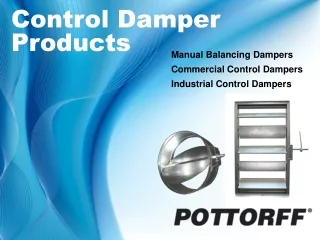
Control Damper Products
Control Damper Products. Manual Balancing Dampers Commercial Control Dampers Industrial Control Dampers. Control Damper Training. Application.


Control Damper Products
E N D
Presentation Transcript
Control Damper Products Manual Balancing Dampers Commercial Control DampersIndustrial Control Dampers
Control Damper Training Application Control Dampers are an integral part of every HVAC system. They are positioned manually or automatically to control air volume and temperature throughout the air handling system. Basic Functions• Volume Control - Regulates airflow. • Temperature Control - Maintains desired temperature. • Pressure Control - Maintains desired pressure. (uncommon)
Control Damper Training Volume Control • Branch Dampers Regulates airflow and branches. • Balancing Dampers Limit flow down the duct or through a device by holding damper blades at a specific position (typically via a manual locking quadrant).• Fan Inlet/Outlet Dampers Used to control flow rate to or from the fan.
Basic Mixing Application Basic System Design Control Damper Training Temperature Control Mixing Dampers• Operate as a pair to maintain temperature. • Simultaneously regulates two different air streams - each with different incoming air temperature. • Able to control air temperature and volume.
Typical Side-by-Side Face & Bypass Application Control Damper Training Temperature Control Face & Bypass/Multi-Zone Dampers• Regulates face air (hot or cold) with bypass/return air to maintain temperature. • Arranged side-by-side, top-bottom, or at right angles.
Flat Hat Channel ‘U’ Channel Flanged Control Damper Training Standard Construction Control Dampers have different designs and are constructed from a variety of frames, blades, axles, bearings, blade linkage and other parts to suit the particular application for that damper. FramesFlat Hat Channel‘U’ ChannelFlanged
3-V Blade Airfoil Blade Control Damper Training Blades • Flat, typically for single-blades dampers, low pressure applications.• Triple-V, economical. Low to medium pressure applications. • Airfoil, lower pressure drop, medium to high pressure applications.
Parallel Opposed Control Damper Training Blade Action Parallel• All blades rotate together in the same direction.• Typically two-position control.Opposed• Adjacent blades rotate in opposite directions.• Balancing and modulating control.
Control Damper Training Axles Attached to the damper blade and extend through the damper frame to permit the blades to rotate. • Various sizes, lengths, materials depending upon the application. Bearings Pressed into the damper frame to permit easy rotating Of the damper blade & shaft. • Various types and materials depending upon the application.
Concealed Linkage Exposed Linkage Control Damper Training Blade Linkage Mechanism that connects the blades together.• Concealed - hidden within the frame on one side or the other or in rare cases, both sides of the damper.• Exposed - attached to the blade face.
Direct Drive Jack Shaft Control Damper Training Damper Drive Mechanism Mechanism that drives (operates) - all the blades together. Typically connected to one blade - Drive Blade.• Direct Drive - typically a shaft extending from one side of the damper adjacent to the damper frame.• Jack Shaft - typically a shaft, offset but connected to the drive blade, extending past the side of the damper- used mostly when connecting multiple single-sectioned dampers together.
Control Damper Training Optional Low Leakage Seals • Stainless Steel Jamb Seals - positioned between the end of the blades and the inside of the damper frame and blade edge seals attached to the damper blades. Optional Stainless Steel Construction • Typically standard construction material is galvanized steel. Most models have type 304 stainless steel (only), and a few offer 316.
Control Damper Training Design Basics Manual Balancing • Commonly found at duct branches and used to restrict airflow in the branch to the desired level. Commercial Control • Most common type and widely used for volume and temperature control. Industrial • Employed when the temperature, pressure, or velocity exceed standard commercial damper limits. Units are typically flange mounted directly to the duct or fan housing.
Concealed Operator RCS-10 RCS-10R Integral Sleeve Hand Quadrant CD-10 CD-10IS CD-10R Control Damper Training Manual Balancing Dampers Used to control the flow of air to meet a required volume, temperature and/or pressure. Cable Control • Enables remote damper positioning from within the occupied space. • Available for round and square duct. Quadrant Control • Quieter than diffuser mounted OBD. • With or without integral sleeve. • Requires access to set quadrant.
Exposed Linkage True Round CD-22R Multi-Blade 3-V Blade Airfoil Blade Concealed Linkage Drive Shaft Integral Sleeve True Round CD-25R Single Blade Integral Sleeve Control Damper Training Commercial Control Dampers Blade Type • 3-V Economical - Galvanized Steel • Airfoil Lower Pressure Drop Galvanized Steel or Aluminum • True-Round Blade Action • Parallel - Blades move together in the same direction - 2-position control • Opposed - Adjacent blades turn in opposite directions - Balancing dampers and modulating control
Hat Channel Frame Drive Shaft Jackshaft NoteH = Blade Length H Face & Bypass Dampers Control Damper Training Commercial Control Dampers Multiple Sections • Jackshaft • Bracing - As required • Face & Bypass Vertical Blades • Actuator/Quadrant Access • Thrust Washers
Actuators Electric Pneumatic CD-81R CD-82 Control Damper Training Industrial Control Dampers • Employed when temperature pressure or velocity exceeds commercial damper limitations. • Typically are flanged frame construction and mounted directly to the duct or fan housing. Supplied approx. net I.D. • Are controlled by a manual locking quadrant or by an electric or pneumatic actuator. Actuators are external mount only.• Actuators are normally, but not always larger in size (more powerful - larger torque) than those used for Commercial Control Dampers/
Channel Frame Concealed Linkage Continuous Blade Axle CD-81R Control Damper Training Industrial Control Dampers Blade Type • 3-V • Airfoil (n/a for Pottorff) • True Round Frame Type • Channel
Side Plate Damper with Side Plate Damper with Sleeve Control Damper Training No-Sleeve vs. Sleeve No-Sleeve Dampers • 1/4” under nominal size Side Plate • 12” wide x 16 gauge Sleeved Dampers • 20 gauge sleeve = 1/8” under nominal size, the thicker the sleeve the closer the OD is to nominal size • Optional Transitions: AR (round), AO (oval), AF (Flange) • Labor Saver - Ready to install from factory
Electric Actuators LMB24-SR (Belimo) NF-120 (Belimo) Pneumatic Actuators 331-4826 (Siemens) 331-2998 (Siemens) Control Damper Training Actuators Actuators control the position of the damper based on signals from the: Building Automation System (BAS), Thermostats & Controllers, Pressure Switches and Relays. Location • External or Internal Electric • 2-Position Spring Return • Modulating • 24, 120, 230 VAC Pneumatic • 25 psi control signal
Control Damper Training Actuators Actuator selection is based upon the ability of the actuator to adequately open and close the damper and the amount of torque the actuator can supply. This typically depends upon the following: • Overall damper size. • Velocity of air through the damper. • Static pressure against the damper. • Damper blade type - parallel or opposed: -Normally parallel bladed dampers require more torque to open than opposed but require less torque to close than opposed. • Whether the damper has jamb seals or not. Our dampers are typically rated at 2000fpm and 1” wg.
External Mount Internal Mount Control Damper Training Actuators Depending upon the damper design, most actuators can be mounted either internally or externally.External mount actuators typically require a side plate or a sleeve to mount the actuator. Internal mounts actuators normally require that the damper has offset jack shafting.
Control Damper Training To determine the proper actuator for a damper. Refer to our catalog sheet entitled Louver and Air Control Dampers, in the Actuators and Accessories section. 1. Calculate the square footage of the damper; example, 48” w x 36” h = 12 square feet. 2. Choose type of actuator - example, 2-position, spring return, 120 volt, no internal switch package. 3. Top left section of our catalog sheet see section 2-Position Spring Return, and then see list of actuators under column entitled 120 VAC Model. 4. Determine if the damper has seals or not: • If yes, use the last column and any actuator rated 12 square feet or above (under 120 VAC) is acceptable i.e. FSNF-120 NF-120 AF-120
Control Damper Training 5. From the list you would typically choose the most economical actuator. 6. If the damper has no seals, use the 2nd last column and follow the same steps to determine the list of actuators. Note: If the job site conditions are greater than 2,000 fpm and/or 1” wg, contact the factory so we can calculate the requirements and quote the proper actuator.
SQ-315 LQ-560 Control Damper Training Other Options & Accessories Low Leakage Seals • Stainless steel jamb seal and PVC blade edge seal. Locking Quadrants • Allow the damper blade to be manually positioned and locked in place to supply the desired air volume. Flange Frame • For flush mounting to equipment/wall. 304 Stainless Steel ConstructionPI-50 Dual Position Indicator Switch • Provides damper “open” or “closed” signal for fan interlock.
Control Damper Training Testing Commercial Control Dampers must function in the HVAC System so as to not adversely affect it. Dampers are tested in accordance with AMCA 500-D. Dampers are certified and labeled In accordance with AMCA 511.
Test Samples • Leakage: Max-Max, Min-Max, Max-Min. • Pressure Drop: 12x12, 12x48, 48x12, 24x24, 36x36. Leakage Rating Pressure Drop • Ducted Inlet & Outlet - AMCA 5.3 Lowest Pressure Drop • Ducted Inlet Only - AMCA 5.2 • Plenum Mount - AMCA 5.5 Highest Pressure Drop Maximum Allowed Leakage (cfm/ft2) Class@ 1 in.wg.@ 4 in.wg. 1A 3 8 1 4 8 2 10 20 3 40 80 AMCA 5.3 – Ducted Inlet & Outlet AMCA 5.2Ducted Inlet AMCA 5.5 – Plenum Mount Control Damper Training
Control Damper Training THANK YOU!