
SlideServe
Menu
Preferences
© SlideServe · v2026

Understanding Output Voltage Clipping and Slew Rate in Non-Inverting Op-Amps

mahsa avatar
7 slides · 254 Views · Oct 09, 2014

This guide explores the concepts of output voltage clipping and slew rate limitations in non-inverting operational amplifiers (op-amps). Using a practical example, we demonstrate how the maximum output voltage correlates with the input voltage and the impact of a slew rate of 0.5 V/µs on the output waveform. Additionally, we address factors influencing full-power bandwidth and DC imperfections such as input bias current and offset current, emphasizing the importance of these parameters for effective op-amp design and application.
Understanding Output Voltage Clipping and Slew Rate in Non-Inverting Op-Amps - slide 1
01 / 7Understanding Output Voltage Clipping and Slew Rate in Non-Inverting Op-Amps
1 / 17

Download Presentation

Understanding Output Voltage Clipping and Slew Rate in Non-Inverting Op-Amps
An Image/Link below is provided (as is) to download presentation

Download Policy: Content on the Website is provided to you AS IS for your information and personal use and may not be sold / licensed / shared on other websites without getting consent from its author.Content is provided to you AS IS for your information and personal use only. Download presentation by click this link. While downloading, if for some reason you are not able to download a presentation, the publisher may have deleted the file from their server.During download, if you can't get a presentation, the file might be deleted by the publisher.

E N D

More Related Content

Presentation Transcript
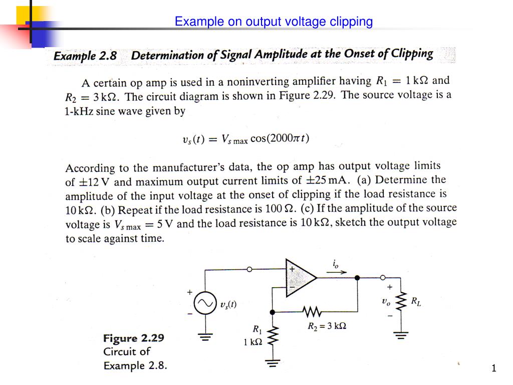
  1. Example on output voltage clipping

  2. Closed loop gain of noninverting op amp (a) (b) Solving, we have V0, max = 2.44 V

  3. (c) Clipping occurs at output voltage of 12 V or input voltage of 3 V

  4. Slew-Rate Limitation As an example, assume we have a waveform, and we have to determine the output of the op-amp having a slew rate of 0.5 V/s

  5. Full-Power Bandwidth The o/p voltage is: Taking derivative, we have: The maximum rate of the o/p voltage change is then equal to the slew rate: Thus the full-power bandwidth is: Thus, and undistorted full-amplitude sinusoidal voltage is possible only for frequencies less than fFP

  6. DC Imperfections: Input bias current: Input offset current:

  7. Model of op-amp with imperfections Unequal current flowing in the terminals and unequal voltages applied , as seen by an external source applied. Ideal op Amp