Altair ® OptiStruct ®
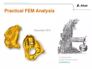
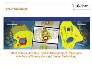
Altair ® OptiStruct ®. Meet Today's Complex Product Development Challenges with Award-Winning Concept Design Technology. But, where is the CAD data coming from ?. CAD. ?. Final Design. CAD import. Geometry cleanup / repair. Prepare geometry according to mesh requirements.

Altair ® OptiStruct ®
E N D
Presentation Transcript
Altair®OptiStruct® Meet Today's Complex Product Development Challenges with Award-Winning Concept Design Technology
But, whereisthe CAD datacomingfrom? CAD ? Final Design • CAD import • Geometrycleanup / repair • Preparegeometryaccordingtomeshrequirements • Meshing, meshqualitychecks • Material, properties (i.e. thickness) • Loads, constraints (boundaryconditions) • Loadstep(s) • Export of FE solver deck • Analysis • Postprocessing
But, whereisthe CAD datacomingfrom? http://www.spiegel.de/video/video-1075437.html • Chirurgen, die entstellte Gesichter rekonstruieren, müssen handwerklich extrem begabt sein: Fehlende Gesichtsknochen werden per Hand modelliert und an den Patienten angepasst. Eine Methode aus dem Bauwesen verspricht jetzt deutlichen Fortschritt für • die plastische Chirurgie.
The CAE Driven Design Process Situation: Yourprofessorasksyouthefollwing: „Forthegivenstucture I needtohave a new, moreinnovative,andlightersolution. Material propertiesremainthe same, however. Deliverydate: Ifpossible, yesterday …“ ? Topologiyoptimization will helpyou
The CAE Driven Design Process Challenges of the early design phase • What if there are no similar or previous designs to reference? • What if the similar design doesn’t scale for the new configuration? • What if you don’t have experience with this type of design? • What if previous designs were never optimized for weight? • What if you have many load cases? • What if you have limited time to make design changes? • What if your engineering judgment leads you down the wrong path? • …
... Innovative or„old“ and well knownsolutions ??? The CAE Driven Design Process Challenges of the early design phase In theconceptphasethedesignerhasmaximum design freedom, but minimum design knowledge 80% of the product weight is determined at the concept design stage
The CAE Driven Design Process Howcanweoptimizethe design without knowingthe design in detail?
The CAE Driven Design Process Topology Optimization – Conceptual Design Setup of optimization problem, definition of design constraints Mesh generation, definition of loads and boundary conditions Computation Interpretation of results CAD Design Definition of available package space
Density = 1 Density = 0 E/E0 1 (r/r0)b 1 r/r0 The CAE Driven Design Process Topology optimization – how does it work? (material) intermediate solutions areavoided • Penalization of intermediate densitythrough power lawb> 1.0 • K(r) = r b Kb = 2 ~ 4 • Where K and K represent the penalized and the real stiffness matrix of an element, respectively, r is the density and b the penalization factor which is always greater than 1. SIMP Method (Solid Isotropic Microstructure with Penalty for Intermediate Density, Bendsøe 1989; Zhou and Rozvany 1990)
The CAE Driven Design Process Optimization – how does it work? The Optimization Problem Statement: • Objective(What do I want?) min f(x) also min [max f(x)] • Design Variables (What can I change?) XiL≤ Xi ≤ XiUi =1,2,3,…N • Design Constraints (What performance targets must be met?) gj(x) ≤ 0 j = 1, 2, 3, …, M
Optimization Terminology The CAE Driven Design Process • Design Variables: System parameters that are varied to optimize system performance. • Design Space: selected parts which are designable during optimization process. For example, material in the design space of a topology optimization • Response: Measurement of system performance. • Objective Function:Any response function of the system to be optimized. The response is a function of the design variables. Ex. Mass, Stress, Displacement, Moment of Inertia, Frequency, Center of Gravity, Buckling factor, and etc. • Constraint Functions: Bounds on response functions of the system that need to be satisfied for the design to be acceptable. • Feasible Design: One that satisfies all the constraints. • Infeasible Design: One that violates one or more constraint functions. • Optimum Design: Set of design variables along with the minimized (or maximized) objective function that satisfy all the constraints.
The CAE Driven Design Process Exercise Determine/find a „lightweight“ design (i.e. withmiminummass) The max. model dimension (design space) isgiven i.e. your design proposal (2Dwithconstantthickness, T= 1mm) maybesmallerormaycontainsholes etc. Restriction: Maximum allowedopeningatthetip: +/- 0.07 mm • F=+/- 100 N max. dimension Material: Steel (E, nu) Usingthe max. design space, theopeningatthetipis +/- 0.02 mm max. dimension
The CAE Driven Design Process Exercise File: Clip_2D_geometry/ clip_geometry.iges max. dimension 1. Think aboutyour design proposal … 2. Import the CAD data in CATIA forCATIA import, youmayneed tochangethefileextensionto*.igs max. dimension 3. Buildyour design in CATIA (Makeuse of symmerty) 4. Export your design as *.igesor *.step 5. Import your design in HyperMesh (CAD data)
The CAE Driven Design Process Exercise File: your_design.iges / step 3 6. Youmayneedtocleanupyour geometry 100 N 7. Meshing 2 1,2,3 8. Define Material, Property, SPC and Loads (Forces), LoadStep 100 N 9. Run analysis 10. Postprocessing and documentation
The CAE Driven Design Process Exercise File: your_design.iges / step 10. Postprocessing and documentation yourdecision *seenextslidesformoreinformation on howtomeasure AREA
HyperMeshIntroduction Measure AREA Select elements
The CAE Driven Design Process Topology optimization - Exercise Base design constraints forces Objective: min. Mass / Volume Restrictions: max. allowableopening (displacement) attip: uy=0.07 mm
The CAE Driven Design Process Topology optimization process - Exercise
The CAE Driven Design Process Topology optimization process - Exercise Interpretation of optimizationresults (by 2 studentdesigners) and re-analysis of theirgiven design Design interpretation I Design interpretation II uy=-0.05 mm uy=-0.07 mm
Display elementdensities (iso-plot) Useslidertoadjustappropriateddensityvalue (i.e. darkblueelementsdisappear)
Super imposecontourplot of displacements (notethatthedisplacementvaluesshownreferto all elements)
To post-processelementsabovedensitythreshold and corresponding displacementsre-runtheanalysis Based on the last optimizationrun e.g. design_29, theresultsfile will benamed: _rst029_s1.h3d