Download
1 / 40
420 likes | 599 Views
Operation and performance of the ATLAS Semiconductor Tracker. Nick Barlow, University of Cambridge, On behalf of the ATLAS SCT collaboration. Contents. Overview of LHC/ATLAS/SCT Design Operational issues Performance Current activities. Introduction.

E N D
Operation and performance of the ATLAS Semiconductor Tracker Nick Barlow, University of Cambridge, On behalf of the ATLAS SCT collaboration.
Contents • Overview of LHC/ATLAS/SCT • Design • Operational issues • Performance • Current activities
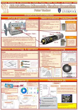
Introduction • The Large Hadron Collider at CERN is the world’s highest energy particle accelerator. • Beams of 4TeV protons can be made to collide head-on at 4 points around the ring, where particle detectors record the results of the collisions.
Introduction • The Large Hadron Collider at CERN is the world’s highest energy particle accelerator. • Beams of 4TeV protons can be made to collide head-on at 4 points around the ring, where particle detectors record the results of the collisions. • ATLAS is the largest of these detectors, designed to study the Standard Model and search for new particles.
Introduction • The Large Hadron Collider at CERN is the world’s highest energy particle accelerator. • Beams of 4TeV protons can be made to collide head-on at 4 points around the ring, where particle detectors record the results of the collisions. • ATLAS is the largest of these detectors, designed to study the Standard Model and search for new particles. • The Inner Detector (ID) is the innermost part of ATLAS, to measure trajectories of charged particles (“tracks”).
ATLAS Inner Detector • The ID consists of: • Pixel detector • Semiconductor Tracker (SCT) • Straw tube tracker (TRT) • All within 2T solenoidal B-field.
ATLAS Inner Detector • The ID consists of: • Pixel detector • Semiconductor Tracker (SCT) • Straw tube tracker (TRT) • All within 2T solenoidal B-field. • Pixel and SCT kept cold by evaporative cooling, using C3F8
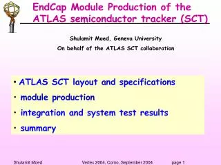
ATLAS Inner Detector • The ID consists of: • Pixel detector • Semiconductor Tracker (SCT) • Straw tube tracker (TRT) • All within 2T solenoidal B-field. • Pixel and SCT kept cold by evaporative cooling, using C3F8 • The SCT is made up of 4 cylindrical barrel layers and 9 endcap disks on each side.
ATLAS Inner Detector • The ID consists of: • Pixel detector • Semiconductor Tracker (SCT) • Straw tube tracker (TRT) • All within 2T solenoidal B-field. • Pixel and SCT kept cold by evaporative cooling, using C3F8 • The SCT is made up of 4 cylindrical barrel layers and 9 endcap disks on each side. • Consists of 4088 double-sided silicon modules. • ‘p-in-n’ silicon strip sensors.
ATLAS Inner Detector and SCT • The ID consists of: • Pixel detector • Semiconductor Tracker (SCT) • Straw tube tracker (TRT) • All within 2T solenoidal B-field. • Pixel and SCT kept cold by evaporative cooling, using C3F8 • The SCT is made up of 4 cylindrical barrel layers and 9 endcap disks on each side. • Consists of 4088 double-sided silicon modules. • ‘p-in-n’ silicon strip sensors. • Each module side has: • 768 aluminium strips (pitch=80 microns) • (>6 Million channels in total!) • 6 ABCD3TA ASIC readout chips. • The 2 sides of a module have stereo angle of 40mrad between strip directions, in order to give 2D position of “hits”.
SCT readout / Data Acquisition (DAQ) • Data from the SCT are read out by off-detector electronics in eight DAQ crates. • Trigger signals received via optical link to Trigger and Timing Crate (TTC).
SCT readout / Data Acquisition (DAQ) • Data from the SCT are read out by off-detector electronics in eight DAQ crates. • Trigger signals received via optical link to Trigger and Timing Crate (TTC). • Trigger and clock signals sent to modules along optical “TX” link (one fibre per module).
SCT readout / Data Acquisition (DAQ) • Data from the SCT are read out by off-detector electronics in eight DAQ crates. • Trigger signals received via optical link to Trigger and Timing Crate (TTC). • Trigger and clock signals sent to modules along optical “TX” link (one fibre per module). • Modules then return hit data along “RX” link (one fibre per side)
SCT readout / Data Acquisition (DAQ) • Data from the SCT are read out by off-detector electronics in eight DAQ crates. • Trigger signals received via optical link to Trigger and Timing Crate (TTC). • Trigger and clock signals sent to modules along optical “TX” link (one fibre per module). • Modules then return hit data along “RX” link (one fibre per side) • Binary readout – either “1” or “0” in each 25ns time bin, depending on whether or not charge exceeded a configurable threshold.
SCT readout / Data Acquisition (DAQ) • Data from the SCT are read out by off-detector electronics in eight DAQ crates. • Trigger signals received via optical link to Trigger and Timing Crate (TTC). • Trigger and clock signals sent to modules along optical “TX” link (one fibre per module). • Modules then return hit data along “RX” link (one fibre per side) • ROD assembles and formats data from 48 modules, then sends along “S-link” to ‘ROS’ (central ATLAS DAQ).
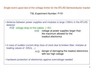
Redundancy in optical communications • Two types of redundancy implemented, in case of failure of optical transmitter or damage to optical fibre. • TX redundancy: module can receive clock and command signals electronically from neighbouring module. • Cannot “daisy-chain” – if two adjacent modules lose optical input on TX line, we will lose data from at least one. • RX redundancy: both sides of a module can be read out through one RX link. • In most barrel modules, this involves bypassing one chip – lose data from 128 strips.
Timing • Upon receipt of a trigger (via TX line), the ABCD will send back (along RX)data from the last three 25ns time bins in its “pipeline” • If we are correctly “timed in”, middle one should correspond to same bunch crossing as event that fired the trigger. • Need to adjust delay to trigger signal module-by-module to account for fibre lengths and time-of flight. • Timing scan performed once or twice per year to find optimum delays.
LHC/ATLAS operations • High instantaneous lumi leads to up to 40 pp interactions per bunch crossing (μ). • High detector occupancy. • Non-zero rate of Single Event Upsets (SEUs) • LHC delivered: • 40nb-1 in 2010 • 5fb-1 in 2011 • 22fb-1 in 2012 • 50ns bunch spacing. • ATLAS Trigger system selects interesting events. • “Level 1” hardware trigger, rate ~70kHz • Detector subsystems must read out their data at this rate! • Software-based High Level Trigger further reduces rate to 400Hz for data recording.
SCT operations • SCT bias voltage maintained at safe 50V level until “Stable Beams” declared, at which point HV is ramped to 150V. • Automated action in 2012, though with shifter oversight. • 99% of readout channels operational. • Automatic recovery (reconfiguration) of modules giving persistent readout errors. • Reconfiguration of all modules every 30 minutes during running (recover from SEUs).
Operational issues – ROD busy • If, for any reason, a ROD is not able to send data to ROS fast enough to keep up with L1 trigger rate, it can assert “BUSY”, which will stop triggers. • Will then be automatically “stoplessly removed”, and can then be recovered by a shifter action. • If >1 SCT ROD is out of the readout at the same time, data is considered “bad” for physics. • Running at high trigger rates and large occupancies uncovered a flaw in our ROD firmware, such that a ROD could go BUSY if a small number of modules returned no data, or too much data, or nonsensical data. • Several issues in ROD firmware were identified and fixed, but problem persisted until the end of the Run. • High priority for detailed investigation during current shutdown!
Operational issues: CiS modules • Approximately 25% of endcap modules manufactured by CiS (remainder manufactured by Hamamatsu). • Slightly different design: • In May 2012, we started observing strange behaviour from some of these modules. • About 2hrs into high-lumi runs, leakage current would increase dramatically, and one side of module would become noisy. • Eventually ROD would go BUSY, and/or module HV would trip. • Could be mitigated in the short term by reducing HV from 150V.
CiS modules • Mainly affected side 0 of “middle” modules. Side 0 Outer • Problem still not fully understood, but was mitigated for 2012 running by reducing “Standby” voltage (HV during inter-fill periods) from 50V to 5V for all CiS modules. • Current would still increase during run, but would plateau before reaching problematic levels. Middle Side 0 Side 0 Inner
Operational issues – TX failures • TX channels (each corresponding to one module) on TX plugins began failing in 2009. • Analysis of failed units indicated ESD damage during manufacturing process. • Replacements ordered, with improved ESD precautions during manufacturing, and installed. • After ~3 months operation, replacements also began to fail. • Some evidence that humidity was damaging the units. • Replacements ordered from a different vendor, with improved resistance to humidity. • TX failures continued during 2012 run (though at a lower rate). • Believed to be due to thermal mismatch between epoxy and VCSEL array. • Third full set of replacements, using a commercial VCSEL package (LightABLE engine), will be installed during the current shutdown period. • Minimal quantity of data was lost due to this problem, due to provision of TX redundancy (modules can receive clock and command signals electronically from neighbouring modules), and vigilance of shifters and on-call experts.
Efficiency • Define intrinsic hit efficiency as “hits-per-possible-hit”, i.e. ignore non-operational modules from both numerator and denominator. • To measure efficiency of each module side, perform track fits ignoring that side, and then see if we see a hit. • Efficiency well above 99% for all layers+sides!
Noise • Too many fake hits from noise could impair the pattern recognition in tracking software. • SCT was designed to have noise occupancy lower than 5x10⁻⁴. • Occupancy can be measured either in standalone calibration runs, or as part of normal ATLAS data-taking (look in empty bunch-crossings). • Noise is well within design limits. • (At high luminosity, there are many more hits from low pT tracks (inc “loopers”) than from intrinsic noise.)
Tracking performance • Up to 4,000 tracks per event in high-pile-up conditions seen in 2012! • Excellent agreement between data and Monte Carlo simulation.
Alignment • Track-based alignment is iterative process, where residuals (i.e. difference in position between hit-on-track and the track intersection point) are minimized. • First align large structures, e.g. SCT wrt TRT and Pixel, then eventually go down to individual modules. • Alignment in Barrel region, particularly in horizontal (“x”) direction, was already good in 2009 as a result of cosmics running.. • SCT is now close to perfectly aligned.
Frequency Scanning Interferometer • Laser-based alignment system, can precisely track distances between nodes. • Large movements observed by FSI can alert track-based alignment team that a new set of constants may be needed.
Lorentz Angle • In absence of B-field, charge carriers produced by ionization of the silicon would be expected to travel in direction of E-field, i.e. perpendicular to surface of sensor. • Solenoidal B-field will deflect charge carries by some angle – Lorentz Angle. • Can be measured by looking at distribution of <cluster-size>-vs-incident angle Lorentz Angle Charge carriers Incidence Angle
Radiation damage • Ionising radiation can have several effects on silicon sensors, including: • Increased leakage current. • Charge trapping / defects • Transition from n-type to p-type. • FLUKA simulation indicates that dose received to date is still some way short of that required for type inversion.
Radiation damage • Radiation damage will increase the leakage current across the silicon sensors. • This can be measured by the Power Supplies, and compared to model predictions, as a function of dose received (using FLUKA and Hamburg/Dortmund model) • Excellent agreement for barrel modules over several orders of magnitude! • Agreement in endcap is less spectacular, but still within 20%. • Radiation damage is not yet having a significant impact on the operating characteristics of SCT modules. • Dose received does not necessitate keeping SCT cold during current shutdown period.
SCT DAQ Bottlenecks For LHC Run 2, will need to handle μ~80, and trigger rate of 100 kHz! S-link: 32bit wide transfer at 40MHz = 1.28Gbps Sufficient for 100kHz readout with m~30-40 ROS x8 ROD input decoder and FIFO: 512 deep ABCDs: 8-deep event buffer, read out at 40Mbps Sufficient for 100kHz L1 with m~87 ROD/BOC pair x90
Expanded ROD System after shutdown 90128 RODs Improved data compression on ROD Bandwidth matches that of front-end S-link: 32bit wide transfer at 40MHz = 1.28Gbps Sufficient for 100kHz readout with m~87 ROS x12 ROD input decoder and FIFO: 512 deep ABCDs: 8-deep event buffer, read out at 40Mbps Sufficient for 100kHz L1 with m~87 ROD/BOC pair x128
Ongoing updates/improvements (cooling and TX transmitters) • Evaporative cooling upgraded to use new thermosyphon system. • Use 90m drop from surface to cavern to provide pressure. • No moving parts – is expected to be more reliable then current compressor-based system. • All TX plugins will be replaced again. • Commercial VCSEL package, expected to be much more reliable.
Conclusions • The SCT has performed extremely well during LHC Run 1. • 99% readout channels operational. • >99% data “good” for physics analysis. • Efficiency and noise match or exceed design specifications, and effects of radiation damage are in good agreement with model predictions. • Updates to DAQ system, cooling, and optical transmitters under way during the current shutdown. • Expect to have even more robust and reliable system for LHC Run 2, able to deal with even higher occupancies and trigger rates.
Calibration • ROD can also generate triggers for calibration. • Several types of calibration, e.g.: • Opto scans – make sure communication between BOC and modules is working well. • Response Curve – ensure that hit threshold is correctly set to desired charge-on-strip. • Noise occupancy – send lots of triggers, count the hits, to ensure SCT modules are operating within design parameters for noise. • Typically have 1-2 hour periods available for calibration between LHC fills.