Download
1 / 39
390 likes | 525 Views
This presentation by Dave Robinson at the 8th International Hiroshima Symposium discusses the operation and performance of the ATLAS Semiconductor Tracker (SCT), which plays a crucial role in the ATLAS detector's tracking system since its commissioning in 2008. With 61 m² of silicon and over 6 million readout channels, the SCT demonstrates advanced designs for reliability in high-radiation environments. The talk reviews the SCT's architecture, including the innovative ASICs used, thermal management strategies, and the rigorous testing and operational performance since its integration into the LHC physics program.

E N D
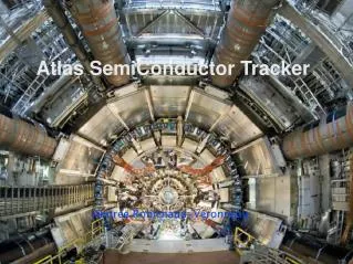
ATLAS Semi Conductor Tracker Operation and Performance Dave Robinson Cavendish Laboratory, Cambridge, UK on behalf of the SCT Collaboration
The ATLAS Detector Tracking in ATLAS ATLAS was fully commissioned in 2008 and has been fully exploiting the physics potential of the LHC since the first 7TeV pp collisions in 2009 Tracking : The Inner Detector Dave Robinson - 8th International Hiroshima Symposium, Academica Sinica, Taipei, 5-8 December 2011
The Semi Conductor Tracker (SCT) • 61 m2 of silicon with 6.2 million readout channels • 4088 silicon modules in 4 Barrels and 18 Disks (9 each end) • Barrels : |h| < 1.1 to 1.4, End-caps : 1.1 to 1.4 <|h| < 2.5 • 30cm < R < 52cm, space point resolution rf ~16mm / R~580mm 1.4m 5.6m • C3F8 Cooling (-7oC to +4.5oC silicon) to limit radiation damage • Radiation hard: tested to 2x10¹⁴ 1-MeV neutron equivalent/cm2 • Lightweight: 3% X0 per layer Dave Robinson - 8th International Hiroshima Symposium, Academica Sinica, Taipei, 5-8 December 2011
The SCTSensors • Single sided p-on-n • <111> substrate, 285mm thick • 768+2 AC-coupled strips • Polysilicon (1.5MW) Bias • Strips reach-through protection 5-10mm • Strip metal/implant widths 22/16mm • 8448 barrel sensors • 64.0 x 63.6mm • 80mm strip pitch • all supplied by Hamamatsu • 6944 wedge sensors • 56.9-90.4mm strip pitch • 5 flavours • 82.8% Hamamatsu • 17.2% CiS (some oxygenated)
The SCT Modules • Back-to-back sensors, glued to highly thermallyconductive substrates for mech/thermal stability,wire-bonded to form ~12cm long strips • 40mrad stereo angle between strips on opposite sides • 1536 channels (768 on each side) • 5.6W/module (rising to ~10W after 10 yrs LHC) • up to 500V sensor bias (nominal 150V) • 2112 barrel modules • one shape • 1976 end-cap modules • 3 shapes
TheASICs (ABCD Chips) • 128 channel ASIC with binary architecture • Radiation-hard DMILL technology • 12 chips per module (6 each side) • glued to hybrid (Cu/polyimide flex circuit) • 40MHz (25ns) clock • 20ns front end shaping time Data Compression Circuit PreAmp+Shaper Readout Buffer Comparator Edge-Detect circuit Binary Pipeline (132 deep) Test-Input DAC • 3 pipeline bins read out, centred on L1A trigger • Hits contained in 1 or 2 bins • Timing optimised using pattern of hits in the 3 time bins Threshold Voltage v “Shaped” input pulse to Comparator t “Logic” output of comparator t
Optical Link Redundancy Schemes Link0 Data Link1 Data VCSEL Standard operation All chips, VCSELs and fibres ok VCSEL TTC P-I-N Link0 Data Link1 Data VCSEL Dead chip bypassed All fibres ok VCSEL TTC P-I-N Link0 Data Link1 Data VCSEL Broken RX fibre or dead RX VCSEL (for barrels, lose master chip of lost link) VCSEL TTC P-I-N Link0 Data Link1 Data VCSEL VCSEL Broken TX fibre or dead TX VCSEL Clock and control from neighbouring module TTC P-I-N Link0 Data Link1 Data VCSEL VCSEL TTC P-I-N Typical snapshot in SCT
The SCT TimelinePrototyping & Production to LHC Physics Dave Robinson - 8th International Hiroshima Symposium, Academica Sinica, Taipei, 5-8 December 2011
Prototyping and Production ≤2003 2004 2005 2006 2007 2008 2009 2010 2011
Assembly of Barrels and End-Caps • mount services - cooling pipes - powering & optical • harnesses • mount modules • connect to services Barrel modules attached by robotat Oxford Cool, power and test all modules after assemblyand compare with pre-assembly data Endcap modules attachedmanually at NIKHEF and Liverpool ≤2003 2004 2005 2006 2007 2008 2009 2010 2011
Reception Tests & Assembly at CERN • Stability & uniformity of cooling and module temperatures • Stability of power supplies and optical communication • Digital functionality, response and noise from all modules • Assembly of all 4 barrels ≤2003 2004 2005 2006 2007 2008 2009 2010 2011
Integration with TRT and combined tests Insertion of SCT barrels within the TRT First cosmic rays recorded throughSCT and TRT ≤2003 2004 2005 2006 2007 2008 2009 2010 2011
Installation and Commissioning in ATLAS cavern Connectivity tests SCT+TRT Barrel installation SCT+TRT End-cap installation ≤2003 2004 2005 2006 2007 2008 2009 2010 2011
Single Beam : “Beam Splash” Events ≤2003 2004 2005 2006 2007 2008 2009 2010 2011
First Collisions at 450 GeV ≤2003 2004 2005 2006 2007 2008 2009 2010 2011
First Collisions at 7 TeV ≤2003 2004 2005 2006 2007 2008 2009 2010 2011
Routine pp Data Taking at 7TeV and 1380 bunches Typical event with 11 vertices (Smallest separation here 3.2mm) ≤2003 2004 2005 2006 2007 2008 2009 2010 2011
SCT Performance Data Quality and Data taking efficiency Data Acquisition Timing Hit Efficiency Lorentz Angle Alignment Operational Issues Dave Robinson - 8th International Hiroshima Symposium, Academica Sinica, Taipei, 5-8 December 2011
Data Quality & Operational Efficiency 2011 2010 Dave Robinson - 8th International Hiroshima Symposium, Academica Sinica, Taipei, 5-8 December 2011
Typical SCT Configuration Status Dave Robinson - 8th International Hiroshima Symposium, Academica Sinica, Taipei, 5-8 December 2011
Data Taking • Several enhancements to DAQ during 2010/11 to maximise data taking efficiency: • “Stopless” reconfiguration and re-integration of RODs in case of (rare) BUSY • Auto reconfiguration & recovery of modules which have non-zero errors • Auto reconfiguration of entire SCT to counter SEUs Typical data link error rate
Hit Efficiency • #Hits/#Possible hits on tracks • Require PT>1GeV/c • Require ≥7 hits for SCT standalone • Require ≥ 6 hits for ID combined • Hit efficiency well above 99% design requirement Dave Robinson - 8th International Hiroshima Symposium, Academica Sinica, Taipei, 5-8 December 2011
Lorentz Angle • Carrier drift direction is deflected in B-field • Lorentz angle - track incidence angle at which the minimum cluster size (#hits in cluster) is detected • Lorentz angle is function of • B-field, voltage and temperature • Prediction sensitive to: • model of signal digitisation in simulation • radiation damage • Measurements with cosmic ray and collision data both compatible with model predictions Dave Robinson - 8th International Hiroshima Symposium, Academica Sinica, Taipei, 5-8 December 2011
Alignment Alignment performed using a track based algorithm (minimisec2 of track-hit residuals). Initial alignment from survey and cosmic ray data, then isolated high Pt tracks for collision data. Continues to improve and approach design values. Dave Robinson - 8th International Hiroshima Symposium, Academica Sinica, Taipei, 5-8 December 2011
Calibration • Charge injection circuitry in ABCD • Measures hits vs threshold (S-curve) • Fit by complementary error function • Noise parameterised by width • SCT noise < 1500 electrons (Hit threshold ~6000 electrons) • Online method • Counts hits in empty bunches • Noise occupancy ~10-5 Design < 5x10⁻⁴ Dave Robinson - 8th International Hiroshima Symposium, Academica Sinica, Taipei, 5-8 December 2011
TX VCSEL issues • SCT has experienced poor reliability and frequent failures of the VCSEL arrays in the TX optical transmitters • Initially attributed to poor ESD precautions at factory • New batch was installed in 2009 manufactured with improved ESD precautions • New batch had improved lifetime, but again started to fail, this time attributed to exposure to humidity • Gradually being replaced by TXs with VCSELs from new vendor with improved resistance against humidity Use of redundancy has minimised impact on SCT operations, and BOCs now operate in lower humidity environment Dave Robinson - 8th International Hiroshima Symposium, Academica Sinica, Taipei, 5-8 December 2011
Radiation Damage • Radiation damages sensors and components. Effects are monitored constantly to predict future performance. • Fluence is measured on-detector • Observe excellent agreement between measured leakage current and predictions from MC based on measured fluence Operationally, we see a gradual and continuous increase in leakage current for each module, both at 50V standby and 150V operation. Trips limits incremented (so far from 5mA to 50mA) appropriately as required. So far expect negligible shift in depletion voltage. 150V 50V Typical module current evolution at 50V and 150V Dave Robinson - 8th International Hiroshima Symposium, AcademicaSinica, Taipei, 5-8 December 2011
Summary • The SCT has enjoyed an outstanding first two years of LHC physics • 99.6% overall data taking efficiency for 2011 • 99.0% of the 6 million channels are operational • Fulfilled design requirements for noise, hit efficiency, tracking and alignment • Significant effects of radiation damage are in very good agreement with expectations • Only significant operational issues have been related to TX VCSEL deaths • Minimal effect on acceptance due to availability of redundancy • Replacement program underway with improved resistance to humidity (and now operate in lower humidity environment) • We look forward to many more years of successful tracking at higher energy and luminosity Dave Robinson - 8th International Hiroshima Symposium, AcademicaSinica, Taipei, 5-8 December 2011
Backup Slides Dave Robinson - 8th International Hiroshima Symposium, Academica Sinica, Taipei, 5-8 December 2011
BOC BOC BOC BOC BOC BOC BOC BOC BOC BOC BOC BOC ROD ROD ROD ROD ROD ROD ROD ROD ROD ROD ROD ROD ROD ROD ROD ROD ROD ROD ROD ROD ROD ROD ROD ROD RX chans RX chans RX chans RX chans RX chans RX chans RX chans RX chans RX chans RX chans RX chans RX chans TX Chans TX Chans TX Chans TX Chans TX Chans TX Chans TX Chans TX Chans TX Chans TX Chans TX Chans TX Chans Optical Communication & Power Supplies 88 Power Supply Crates 8 ROD crates (90 ROD/BOC pairs) LV: - Vdd - Vcc - Vvcsel - Vpin HV: - Vbias DCS 48 modules per ROD/BOC DATA SCT Module VCSEL VCSEL P-I-N TTC P-I-N receives Timing, Trigger & Control VCSEL* for each link (side) returns data ROD crate (DAQ) * VCSEL=Vertical Cavity Surface Emitting Laser
Dave Robinson - 8th International Hiroshima Symposium, Academica Sinica, Taipei, 5-8 December 2011
Timing The ABCD chip is a binary chip - “hit” or “no hit” above 1fC threshold. It samples hits in 3 consecutive time bins (25ns LHC clock cycles), and is configured to flag a “hit” in the readout depending on the pattern of hits in those 3 bins • Three bin sampling provides means to time in the SCT, and provide rejection of ghost tracks from hits associated with collisions 25ns or 50ns earlier. • XXX for timing in, cosmic rays and ≥75ns bunch trains • X1X used currently for 50ns bunch trains • 01X will be used for 25ns bunch trains • Dedicated timing scans in first low lumi pp collisions of the year, with each of the 4088 modules optimised for 01X (1ns precision) Mean of 3bit hit pattern across SCT Dave Robinson - 8th International Hiroshima Symposium, AcademicaSinica, Taipei, 5-8 December 2011
Occupancy and Rate Limitations (*ATLAS 7/415) • We expect around 1% peak SCT occupancy for 23 interactions per BX at 14TeV • Rate limit at 1% occupancy is ~90kHz, comfortably above ATLAS nominal peak trigger rate of 75kHz (*) Complex Dead-Time: Maximum number of triggers within a given number of bunch crossings -> Imposed by ABCD 8-deep event buffer
Cooling & Environment The C3F8 evaporative cooling system has operated very reliably all year. But…. • C3F8 Compressor Issues • Worries about long term reliability have motivated the Thermosiphon project • Gravity fed C3F8 system, to be commissioned in long 2013/14 shutdown • Cooling temperatures • Pressure gradient in long delivery lines means the SCT silicon cannot reach the design operating temperature of -7oC • Fluorocarbon blends (C3F8-C2F6) will allow is to reach target temperature • Thermo-heater Pad issues • Some non-operational heater pads (between SCT and TRT) requires us to run barrel 6 (outermost barrel) at elevated temperature Dave Robinson - 8th International Hiroshima Symposium, Academica Sinica, Taipei, 5-8 December 2011
Frequency Scanning Interferometry • Optical alignment system to monitor the long term SCT mechanical stability • 842fibre coupled interferometers • Typical deviations associated with solenoid cycle: • - before ~11nm • - during <3mm • - after ~49nm Dave Robinson - 8th International Hiroshima Symposium, Academica Sinica, Taipei, 5-8 December 2011
The SCT CiS Sensors – “Same spec, different species” Dave Robinson - 8th International Hiroshima Symposium, Academica Sinica, Taipei, 5-8 December 2011
The CIS Leakage Current Problem • It become clear that the CIS SCT sensors were very sensitive to humidity • A significant subset displayed poor IV and early (<150V) breakdown in dry conditions • Need humidity to maintain a ‘healthy looking’ IV • Became more apparent during module tests which (unlike sensor QA) were typically conducted in nitrogen environment • Problem identified as microdischarge from strips, due to lack of field plate (strip metal narrower than implant) • As this became an issue rather late in the delivery program, SCT adopted a pragmatic strategy: • Only accept sensors with no sign of breakdown below 150V in dry air • OK for the short term, and then strip micro-discharge becomes less relevant after type inversion Dave Robinson - 8th International Hiroshima Symposium, Academica Sinica, Taipei, 5-8 December 2011
CIS Leakage Current ProblemConsequences during SCT operation • We have had a small but significant (~30) number of modules which have developed anomalously high leakage currents this year • Almost all were constructed with CIS sensors, and all showed IV breakdown above 150V during production QA tests • We believe that oxide charge buildup from ionising radiation is shifting the breakdown voltage downwards • Decreasing HV and increasing current limits means we can keep operating these devices with full efficiency so far Dave Robinson - 8th International Hiroshima Symposium, Academica Sinica, Taipei, 5-8 December 2011
Comparison of 1MeV neutron equivalent fluences determined from SCT leakage current measurements with simulated FLUKA Snapshot corresponding to 2010 7TeV data with integrated luminosity of 48.6pb-1 Excellent agreement for barrels. Reasonable agreement for end-caps Dave Robinson - 8th International Hiroshima Symposium, Academica Sinica, Taipei, 5-8 December 2011