PROCESS DESIGN TOOLS
PROCESS DESIGN TOOLS. NCP has traditionally used Bond Models to size Ball mills. We still utilize a modified version of Bond Theory for Ball Mill Sizing. SAG/AG mills are sized using a hybrid model including published information from Barrett, Austen & Morrell.

PROCESS DESIGN TOOLS
E N D
Presentation Transcript
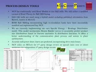
PROCESS DESIGN TOOLS • NCP has traditionally used Bond Models to size Ball mills. We still utilize a modified version of Bond Theory for Ball Mill Sizing. • SAG/AG mills are sized using a hybrid model including published information from Barrett, Austen & Morrell. • ROM Ball Milling incorporating high re-circulation loads have been successfully modeled and implemented buy NCP. • We are currently implementing our own Specific Energy / Breakage Distribution model. This model incorporates RossinRamler curves to accurately predict product size distributions based on fracture mechanics & distribution functions. It offers a better understanding of the communication plant process and assists in plant optimization. • Accurate mill power draw charts are predicted, incorporating drive train losses. • NCP relies on JKTech for 3rd party design review on special cases ores or client preference for independent 3rd party design review.
Structural & MECHANICAL Design TOOLS • FEA is undertaken with a 3-dimensional Structural Finite Element package integrated to our 3D Modeling Package. • NCP’s FEA stress predictions have been independently verified in the field through strain gauging. FEA calculated stresses are proven to be within 12% of actual measured. • The Mill structure is sufficiently designed for any given load in accordance with internationally accepted stress levels in accordance with AAC323001 • Fatigue Analysis is undertaken in accordance with BS7608. • NCP’s design capabilities included Fluid Film Analysis of all Bearing Designs, DEM Charge Analysis & Torsional Analysis of Drive Train for Harmonic Resonance.
CASTING SIMULATIONS Option Study Fill Temperature Fill Velocity Material Solidification
MECHANICAL DESIGN • DRIVE TRAIN INCL COUPLINGS, GEARBOX, PINION & GIRTH GEAR • Coupling designs are sized utilizing SF > 2.0. • Gearbox Designs are submitted for NCP Review to AGMA 2001.C95. • NCP Specification SF > 2.0. • Bearing life L10basic >52,000hrs. • Bearing and Gearmesh lubrication flow rate analysis • Open Gearing designed to AGMA 321.05. • Gear - SFdurability >=1.50. SFstrength = 2.20. • Torsional vibration analysis of the drive trains modelled and harmonal frequencies reviewed prior to selection of critical drive train components. .
DESIGN OVERVIEW ANCILLARY ITEM DESIGN • LUBE SYSTEMS • Lube System design will be undertaken by NCP based on NCP Osborn design Specification. • Flow rates are established through first principle fluid film analysis. • Each project is unique and a stringent specification is in place to ensure lube systems are designed and supplied fit for the intended purpose. • FEED SPOUT/CHUTE DESIGN • Feed Spout arrangements are designed according to discharge trajectory theory & bulk solids chute design principals (Wouter Deijs). Ore specific tests are also conducted for selection of the appropriate wear resistant liners.
DESIGN OVERVIEW ANCILLARY ITEM DESIGN • NCP offers DEM analysis of the mill charge and optimizes liner design and mill operating speed in this manner. • Grate design, if applicable, is optimized including pulp excavation design. • Our design model includes slurry pooling investigations as well as ball entrainment and toe impact investigation. • Charge loads placed on the shell and heads is modeled in dynamic mode which more accurately predicts operating stress than typical static overset charge analysis. These stresses are incorporated into the Mill FEA.