Register
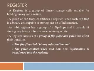
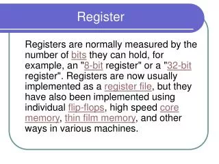
Register. A register is a sequential circuit that can be set to a specific state and retain that state until externally changed. State is a combination of bits Frequently used to perform simple data storage and data movement and processing operations. Register Design.

Register
E N D
Presentation Transcript
Register • A register is a sequential circuit that can be set to a specific state and retain that state until externally changed. • State is a combination of bits • Frequently used to perform simple data storage and data movement and processing operations
Register Design • An S-R latch is a simple 1-bit register. • With (S)et input, latch output can be set to 1 • With (R)eset input, latch output can be set to 0.
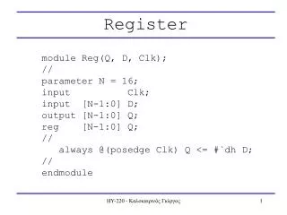
Register Design • A D flip-flop can be used as a 1-bit register • Input 0, output is set to 0 when flip-flop is clocked • Input 1, output is set to 1 when flip-flop clocked • Can consider the clock to be a load signal. • On rising edge of load signal, the data on D input line is stored in the flip-flop
Register Storage • Expectations: • A register can store information for multiple clock cycles • To “store” or “load” information should be controlled by a signal • Reality: • A D flip-flop register loads information on every clock cycle • Realizing expectations: • Use a signal to block the clock to the register, • Use a signal to control feedback of the output of the register back to its inputs, or • Use other SR or JK flip-flops which for (0,0) applied store their state • Load is a frequent name for the signal that controls register storage and loading • Load = 1: Load the values on the data inputs • Load = 0: Store the values in the register
Registers with Load-Controlled Feedback • A more reliable way to selectively load a register: • Run the clock continuously, and • Selectively use a load control to change the register contents. • Example: 2-bit registerwith Load Control: • For Load = 0,loads register contents(hold current values) • For Load = 1,loads input values(load new values) • Hardware more complexthan clock gating, butfree of timing problems 2-to-1 Multiplexers A1 Y1 Q D Load In1 C A0 Y0 Q D C In0 Clock
d inputs c b a • Da Dd Dc Db Ck Qd Ck Qa Ck Qb Ck Qa load outputs d c b a Multibit Register • Use multiple flip-flops. Each stores a single bit. • Common load signal.
Shift Registers • Shift Registers move data laterally within the register toward its MSB or LSB position • In the simplest case, the shift register is simply a set of D flip-flops connected in a row like this: • Data input, In, is called a serial input or the shift right input. • Data output, Out, is often called the serial output. • The vector (A, B, C, Out) is called the parallel output.
Shift Registers (continued) CP In A B C Out T0 0 ? ? ? ? T1 1 0 ? ? ? T2 1 1 0 ? ? T3 0 1 1 0 ? 0 1 1 0 T4 1 1 0 1 1 T5 1 1 1 0 1 T6 1 • The behavior of theserial shift registeris given in the listingon the lower right • T0 is the register state just before the first clockpulse occurs • T1 is after thefirst pulse andbefore the second. • Initially unknownstates are denoted by “?” B A C Out In D Q D Q D Q D Q Clock CP