Overview of the ARIES Fusion Power Plant Studies Program
420 likes | 621 Views
Overview of the ARIES Fusion Power Plant Studies Program. Mark Tillack http://aries.ucsd.edu/ARIES July 3, 2001 CIEMAT, Madrid. ARIES is the Primary Venue in the US for Conceptual Design & Assessment of Fusion Power Plants. Mission Statement:

Overview of the ARIES Fusion Power Plant Studies Program
E N D
Presentation Transcript
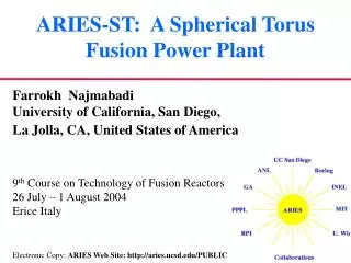
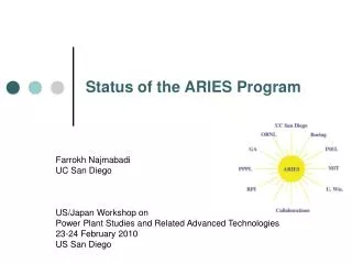
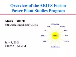
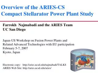
Overview of the ARIES Fusion Power Plant Studies Program Mark Tillack http://aries.ucsd.edu/ARIES July 3, 2001 CIEMAT, Madrid
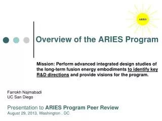
ARIES is the Primary Venue in the US for Conceptual Design & Assessment of Fusion Power Plants • Mission Statement: Perform advanced integrated design studies of long-term fusion energy embodiments to identify key R&D directions and provide visions for the program. What is important Physics & Technology R&D Programs ARIES Program What is possible Systems studies are performed to identify not just the most effective experiments for the moment, but also the most cost-effective pathways to the evolution of the experimental, scientific and technological program.
The National ARIES Program Allows Fusion Scientists to Investigate Fusion Systems as a Team • Universities (~2/3), national laboratories, and private industry contribute. • Decisions are made by consensus. • The team is flexible: expert groups and advocates are involved as needed to ensure the flow of information to/from R&D programs. e.g., ARIES-AT Participants: Argonne National Laboratory Boeing High Energy Systems General Atomics Idaho National Eng. & Environmental Lab. Massachusetts Institute of Technology Princeton Plasma Physics Laboratory Rensselaer Polytechnic Institute University of Wisconsin - Madison Forschungszentrum Karlsruhe University of California, San Diego Because it draws its expertise from the national program, ARIES is unique in its ability to provide a fully integrated analysis of power plant options including plasma physics, fusion technology, economics, safety, etc.
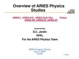
Conceptual Designs of Fusion Power Systems Are Developed Based on a Reasonable Extrapolation of Physics & Technology Attractiveness tradeoff Feasibility (risk) • Plasma regimes of operation are optimized based on latest experimental achievements and theoretical predictions. • Engineering system design is based on “evolution” of present-day technologies, i.e., they should be available at least in small samples now. Only learning-curve cost credits are assumed in costing the system components. • Program continuity allows concept comparisons on an even playing field.
Fusion must demonstrate that it can be a safe, clean, & economically attractive option • Gain Public acceptance: • Use low-activation and low toxicity materials and care in design. • Have operational reliability and high availability: • Ease of maintenance, design margins, and extensive R&D. • Have an economically competitive life-cycle cost of electricity: • Low recirculating power; • High power density; • High thermal conversion efficiency; • Less expensive systems.
Top-Level Requirements for Commercial Power Plants Were Developed through Interaction with Representatives from U.S. Electric Utilities and the Energy Industry No public evacuation plan is required: total dose < 1 rem at site boundary; Generated waste can be returned to environment or recycled in less than a few hundred years (not geological time-scale); No disturbance of public’s day-to-day activities; No exposure of workers to a higher risk than other power plants; Closed tritium fuel cycle on site; Ability to operate at partial load conditions (50% of full power); Ability to maintain power core; Ability to operate reliably with less than 0.1 major unscheduled shut-down per year. Above requirements must be achieved consistent with a competitive life-cycle cost of electricity goal.
The ARIES Team Has Examined Several Magnetic Fusion Concepts as Power Plants in the Past 12 Years • TITAN reversed-field pinch (1988) • ARIES-I first-stability tokamak (1990) • ARIES-III D-3He-fueled tokamak (1991) • ARIES-II and -IV second-stability tokamaks (1992) • Pulsar pulsed-plasma tokamak (1993) • SPPS stellarator (1994) • Starlite study (1995) (goals & technical requirements for power plants & Demo) • ARIES-RS reversed-shear tokamak (1996) • ARIES-ST spherical torus (1999) • Fusion neutron source study (2000) • ARIES-AT2advanced technology and advanced tokamak (2000) • IFE chamber assessment (ongoing)
ARIES-RS and ARIES-AT are conceptual 1000 MWe power plants based on reversed-shear tokamak plasmas
The ARIES-RS Study Set the Goals and Direction of Research for ARIES-AT
Major Parameters of ARIES-RS and ARIES-AT ARIES-RS ARIES-AT Aspect ratio 4.0 4.0 Major toroidal radius (m) 5.5 5.2 Plasma minor radius (m) 1.4 1.3 Toroidal b 5%*9.2%* Normalized bN 4.8* 5.4* Plasma elongation @xp (kx) 1.9 2.2 Plasma current 11 13 Toroidal field on axis 8.0 5.9 Peak field at TF coil (T) 16 11.1 Peak/Avg. neutron wall load (MW/m2) 5.4/4 4.9/3.3 Thermal efficiency 0.46 0.59 Fusion power (MW) 2,170 1,755 Current-drive power to plasma (MW) 81 36 Recirculating power fraction 0.17 0.14 Cost of electricity (1992 ¢/kWh) 7.5 5.0 • Designs operate at 90% of maximum theoretical b limit.
The ARIES-RS Replacement Sectors are Integrated as a Single Unit for High Availability • No in-vessel maintenance operations • Strong poloidal ring supporting gravity and EM loads. • First-wall zone and divertor plates attached to structural ring. • No rewelding of elements located within radiation zone • All plumbing connections in the port are outside the vacuum vessel. Key Features:
The Divertor Structures Satisfy Several Functions • Mechanical attachment of the divertor plates • Magnet shielding • Coolant routing for the plates and inboard blanket • “Superheat” of the divertor coolant • Important contribution to the breeding ratio
The ARIES-AT Blanket Utilizes a 2-Pass Coolant to Uncouple Structure from Outlet Coolant Temperature • Maintain blanket SiC/SiC temperature (~1000°C) < Pb-17Li outlet temperature (~1100°C) • 2-pass Pb-17Li flow, first pass to cool SiC/SiC box and second pass to “superheat” Pb-17Li
The ARIES-ST Study Identified Key Directions for Spherical Tokamak Research • Substantial progress was made towards optimization of ST equilibria with >95% bootstrap fraction: • b = 54%, k = 3; • A feasible center-post design has been developed; • Several methods for start-up has been identified; • Current-drive options are limited; • 1000-MWe ST power plants are comparable in size and cost to advanced tokamak power plants.
Major Parameters of ARIES-ST Aspect ratio 1.6 Major radius 3.2 m Minor radius 2 m Plasma elongation, kx 3.75 Plasma triangularity, dx 0.67 Plasma current 28 MA Toroidal b 50% Toroidal field on axis 2.1 T Avg. neutron wall load 4.1 MW/m2 Fusion power 2980 MW Recirculating power 520 MW TF Joule losses 325 MW Net electric output 1000 MW
ARIES-ST Utilizes a Dual Coolant Approach to Uncouple Structure Temperature from Main Coolant Temperature • ARIES-ST: Ferritic steel+Pb-17Li+He • Flow lower temperature He (350-500°C) to cool structure and higher temperature Pb-17Li (480-800°C) for flow through blanket
Spherical Torus Geometry Offers Some Unique Design Features (e.g., Single-Piece Maintenance)
Inboard shield on a spherical torus Previous perception: Any inboard (centerpost) shielding will lead to higher Joule losses and larger/more expensive ST power plants. Conclusions of ARIES study: A thin (20 cm) shield actually improves the system performance . • Reduces nuclear heating in the centerpost and allows for a higher conductor packing fraction • Reduces the increase in electrical resistivity due to neutron-induced transmutation • Improves the power balance by recovering high-grade heat from the shield • Allows the centerpost to meet the low-level waste disposal requirement with a lifetime similar to the first wall (more frequent replacement of the centerpost is not required). ARIES-ST power core replacement unit
Impact of latest developments in many scientific disciplines are continuously considered, and play an important role in the attractiveness of fusion Examples: • SiCf/SiC composite materials • High-temperature Brayton power conversion cycles • Advanced manufacturing techniques • High-Tc superconductors • Reliability, availability and maintainability
Recent Advances in Brayton Cycle Lead to Power Cycles With High Efficiency • Conventional steam cycle 35% steel/water • Supercritical steam Rankine 45% Li/V • Low-temperature Brayton >45% advanced FS/PbLi/He • High-temperature Brayton 60% SiC/He • A key improvement is the development of cheap, high-efficiency recuperators.
Revolutionary Fabrication Techniques May Significantly Reduce Fusion Power Core Costs • A laser or plasma-arc deposits a layer of metal from powder. • The laser lays down the material in accordance with a CAD specification. • Like stereo-lithography, construction of overhanging elements should be avoided – tapers up to 60° are possible. • Fabrication of titanium components is being considered for Boeing aircraft to reduce airframe material and fabrication costs. • Properties are equivalent to cast or wrought. • Process is highly-automated (reduced labor). • Process can produce parts with layered or graded materials to meet functional needs. AeroMet has produced a variety of titanium parts. Some are in as-built condition and others machined to final shape.
Fabrication of ARIES-ST Centerposts Using Laser Forming was Assessed • Mass of centerpost with holes plus 5% wastage 894,000 kg • Deposition rate with 10 multiple heads 200 kg/h Total labor hours 8628 h • Labor cost @ $150/h (with overtime and site premium) $1,294,000 • Material cost, $2.86/kg (bulk copper alloy power cost) $2,556,000 • Energy cost (20% efficiency) for elapsed time + 30% rework $93,000 • Material handling and storage $75,000 • Positioning systems $435,000 • Melting and forming heads and power supplies $600,000 • Inert atmosphere system $44,000 • Process computer system $25,000 Subtotal cost of centerpost$5,122,000 • Contingency (20%) $1,024,000 • Prime Contractor Fee (12%) $738,000 Total centerpost cost$6,884,000 • Unit cost (finished mass = 851,000 kg) $8.09/kg Highly Automated Fabrication < 3 x Matl Cost Compare to $80/kg with conventional fabrication ($68M)
Sector Removal Remote equipment is designed to remove shields and port doors, enter port enclosure, disconnect all coolant and mechanical connections, connect auxiliary cooling, and remove power core sector
ARIES-AT Sector Replacement Basic Operational Configuration Cross Section Showing Maintenance Approach Plan View Showing the Removable Section Being Withdrawn Withdrawal of Power Core Sector with Limited Life Components
Reliability can be achieved through sound design principles and testing • Perception of poor availability is based on water-cooled steel, ceramic breeder blanket (Bünde, Perkins, Abdou) • 220 km of pipe • 37,000 butt welds • 5 km of longitudinal welds • Low failure rate is possible through: • Simple design and fabrication • Wide operating margins (T, p, s) • Failure tolerance & redundancy • ARIES-AT • 3680 m of pipe, 1440 braze joints • <1500 m braze length to headers (173 m exposed to plasma) ARIES-AT blanket construction is simple and robust
Individual advances on several fronts help improve the attractiveness of fusion
Our Vision of Magnetic Fusion Power Systems Has Improved Dramatically in the Last Decade, and Is Directly Tied to Advances in Fusion Science & Technology Estimated Cost of Electricity (¢/kWh) Major radius (m) ARIES-AT parameters: Major radius: 5.2 m Fusion Power 1,720 MW Toroidal b: 9.2% Net Electric 1,000 MW Wall Loading: 4.75 MW/m2 COE 5.5 ¢/kWh
ARIES integrated IFE chamber analysis and assessment research started in June 2000 • Analyze & assess integrated and self-consistent IFE chamber concepts • Understand trade-offs and identify design windowsfor promising concepts.The research is not aimed at developing a point design. • Identify existing data base and extrapolations needed for each promising concept. Identify high-leverage items for R&D: • What data is missing? What are the shortcomings of present tools? • For incomplete database, what is being assumed and why? • For incomplete database, what is the acceptable range of data? Would it make a difference to zeroth order, i.e., does it make or break the concept? • Start defining needed experiments and simulation tools.
Tasks Target Physics (NRL*, LLNL*, UW) Chamber Physics (UW, UCSD) Parametric Systems Analysis (UCSD, BA, LLNL) Safety & Env. (INEEL, UW, LLNL) Neutronics, Shielding (UW, LLNL) Final Optics & Transport (UCSD, NRL*,LLNL*, LBL) Target Fab. (GA, LANL*) Target Inj./Tracking (GA) Materials (ANL) Tritium (ANL, LANL*) Drivers* (NRL*, LLNL*, LBL*) Chamber Eng. (UCSD, UW) CAD (UCSD) Fusion Labs * voluntary contributions ARIES-IFE Is a Multi-institutional Effort OFES Program Management F. Najmabadi Les Waganer (Operations) Mark Tillack (System Integration) Executive Committee (Task Leaders) Advisory/Review Committees
We Use a Structured Approach to Asses Driver/Chamber Combinations • Six classes of target were identified. Advanced target designs from NRL (laser-driven direct drive) and LLNL (Heavy-ion-driven indirect-drive) were used as starting points. • To make progress, we divided the activity based on three classes of chambers: • Dry wall chambers; • Solid wall chambers protected with a “sacrificial zone” (such as liquid films); • Thick liquid walls. • We plan to research these classes of chambers in series with the entire team focusing on each. • While the initial effort has focused on dry walls, some of the work is generic to all concepts (e.g., characterization of target yield).
A Year Ago the Feasibility of Dry Wall Chambers Was in Question 1992 Sombrero Study highlighted many advantages of dry wall chambers. General Atomic calculations indicated that direct-drive targets do not survive injection in Sombrero chamber.
Target injection window (for 6-m Xe-filled chambers): Pressure < 10-50 mTorr Temperature < 700 C Target injection Design Window Naturally Leads to Certain Research Directions Chamber-based solutions: Low wall temperature: Decoupling of first wall & blanket temperatures Low gas pressure: More accurate calculation of wall loading & response Advanced engineered material Alternate wall protection Magnetic diversion of ions* Target-based solutions: Sabot or wake shield,Frost coating* * Not considered in detail
Variations in the Chamber Environment Affects the Target Trajectory in an Unpredictable Way ACCELERATOR TRACKING, GAS, & 8 m SABOT REMOVAL STAND-OFF INJECTOR 1000 g 7m 2.5 m ACCURACY Capsule velocity out 400 m/sec Ex-chamber tracking system GIMM R 30 m MIRROR R 50 m CHAMBER TRACKING R 6.5 m ACCURACY T ~1500 C • Forces on target calculated by DSMC Code •“Correction Factor” for 0.5 Torr Xe pressure is large (~20 cm) • Repeatability of correction factor requires constant conditions or precise measurements • 1% density variation causes a change in predicted position of 1000 mm (at 0.5 Torr) • For manageable effect at 50 mTorr, density variability must be <0.01%. • Leads to in-chamber tracking
5 CH 1 m CH +300 Å Au LLNL/LBNL HIF Target CH Foam + DT .162 cm CH Foam + DT .195 cm DT Fuel DT Fuel .144 cm .169 cm .122 cm DT Vapor 0.3 mg/cc DT Vapor 0.3 mg/cc .150 cm CH foam = 75 mg/cc CH foam = 20 mg/cc Reference Direct and Indirect Target Designs NRL Advanced Direct-Drive Targets
Energy Output and X-ray Spectra from Reference Direct and Indirect Target Designs NRL Direct Drive Target (MJ) HI Indirect Drive Target (MJ) X-rays 2.14 (1%) 115 (25%) Neutrons 109 (71%) 316 (69%) Gammas 0.0046 (0.003%) 0.36 (0.1%) Burn product fast ions 18.1 (12%) 8.43 (2%) Debris ions kinetic energy 24.9 (16%) 18.1 (4%) Residual thermal energy 0.013 0.57 Total 154 458 X-ray spectrum is much harder for NRL direct-drive target
Ion Spectra from Reference NRL Laser-Driven Direct –Drive Target Fast Ions Slow Ions
The Spectrum Is Coupled With BUCKY Code to Establish Operating Windows for the First Wall Sombrero >> Chamber gas pressure can be reduced substantially, especially at lower wall temperatures. Dec. 2000 results Time of flight spread in ion-debris energy flux on the wall was not included. Wall vaporizes Wall survives
Ion thermal power on the chamber wall including time-of-flight (6.5-m radius chamber in vacuum) Temporal Distribution of Ion-Debris Energy Flux Allows Operation at 700˚C and Vacuum NRL advanced direct-drive targets with output spectra from LLNL & NRL target codes. Most of heat flux due to fusion fuel and fusion products. Chamber wall with carbon armor and initial tempera-ture of 700 C survives. Results confirmed by Bucky
Advanced Engineered Materials May Provide Superior Damage Resistance Carbon fiber velvet in carbonizable substrate 7–10 mm fiber diameter 1.5-2.5-mm length 1-2% packing fraction • Good parallel heat transfer, compliant to thermal shock • Tailorable fiber geometry, composition, matrix • Already demonstrated for high-power laser beam dumps and ion erosion tests • Fibers can be thinner than the x-ray attenuation length.
Initial Results from ARIES-IFE Have Removed Major Feasibility Issues of Dry Wall Chambers • Research is now focused onOptimization And Attractiveness • Trade-off studies are continuing to fully characterize the design window. We are analyzing response of the chamber to • Higher target yields • Smaller chamber sizes • Different chamber wall armor • Examination of wetted wall concepts is underway
University of California, San Diego School of Engineering Graduate Studies in Plasma Physics & Controlled Fusion Research Current Research Areas: • Theoretical low temperature plasma physics • Experimental plasma turbulence and transport studies • Theoretical edge plasma physics in fusion devices • Plasma-surface interactions • Diagnostic development • Semiconductor manufacturing technology • Theory of emerging magnetic fusion concepts • Fusion power plant design and technology • Radio-frequency heating and current drive • Laser-matter interactions and inertial confinement fusion • Thermo-mechanical design of nuclear fusion reactor components • Theoretical space and astrophysical applications Interested students are encouraged to visit our website at: http://www-ferp.ucsd.edu/brochure.html for information on our research, available financial support and university admissions policy.