Download
1 / 17
190 likes | 744 Views
ME 566 Computer Lab ANSYS–CFX Tutorial Oct. 5, 2009 2:30 – 4:30 pm Wedge E2-1302B. 1. ANSYS CFX Student User Manual. The manual can be downloaded from UW-ACE In the tutorial, you will be working on the Duct Bend Example (Sec. 2.2, pages 13-29) in the manual

E N D
ME 566 Computer Lab ANSYS–CFX Tutorial Oct. 5, 2009 2:30 – 4:30 pm Wedge E2-1302B 1
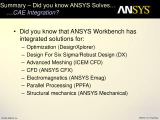
ANSYS CFX Student User Manual • The manual can be downloaded from UW-ACE • In the tutorial, you will be working on the Duct Bend Example (Sec. 2.2, pages 13-29) in the manual • Two mesh generation methods are presented in the manual: • ANSYS Mesh Generation (pages 17-19) • CFX Mesh Generation (pages 27-29) • You should focus on the CFX Mesh Generation method in the tutorial
Overview of ANSYS–CFX DesignModeler Create geometry CFX-Mesh Generate mesh ANSYS Workbench CFX-Pre Pre-processing CFX-Solver Solve equations CFX-Post Post-processing
ANSYS–CFX • DesignModeler: • Define geometry dimensions • Name the faces of the solid body (e.g., inlet, outlet, wall, symmetry) • CFX-Mesh: • Specify mesh properties (e.g., mesh spacing, inflated boundary thickness) • CFX-Pre: • Specify fluid properties (e.g., density, viscosity) • Set simulation type (e.g., steady) • Select turbulence model (e.g., k- model, wall functions) • Specify boundary conditions (e.g., speed, turbulence intensity and length scale) • Select advection scheme (e.g., upwind) • Define convergence criterions (e.g., number of iterations, residual target) • CFX-Solver: • Solve system of partial differential equations • CFX-Post: • Analyze results and create plots (e.g., vector plot)
Duct Bend Example 0.25 m 0.1 m 1 m 0.1 m • The radius of the inner wall bend is 0.025 m • The average speed of the water flow through the duct is 3 m/s 0.1 m
DesignModeler • Create a solid body geometry
DesignModeler – continued • Name the faces of the solid body • to make it easy to apply boundary conditions • In the duct bend example, six faces of the solid body are named as: Front, Back, Inflow, Outflow, InnerWall, OuterWall Back OuterWall Outflow Front InnerWall Inflow
CFX–Mesh • Mesh generation methods • ANSYS Mesh Generation (pp. 17-19): generates a structured mesh • CFX Mesh Generation (pp. 27-29): generates an unstructured mesh • You will use CFX Mesh Generation for Assignment #1 structured mesh unstructured mesh
CFX–Pre • Fluid type and properties • Type: water/air • Properties: density, dynamic viscosity • Simulation type • Steady/transient • Fluid models • Turbulence model (e.g., k- model/shear stress transport model) • Turbulent wall functions (e.g., scalable)
CFX–Pre continued • Specify boundary conditions • Wall: smooth/rough, stationary/translating/rotating • Inlet: fluid speed/mass flow rate/pressure • Outlet: fluid speed/mass flow rate/pressure • Symmetry: • Advection scheme • Upwind/High Resolution • Timescale control • Auto Timescale/Physical Timescale • Convergence criterions • Number of iterations • Residual target
CFX–Pre continued • Estimation of Physical Timescale • The physical timescale is calculated using approximately 30% of the average residence time for a fluid parcel to move across the flow domain (see pages 47 and 48 of the student user manual for reference). • For the duct bend case • Fluid travel length (average): • Flow speed: • Average residence time: • Physical timescale: 0.125 m 0.025 m 0.25 m 0.1 m 0.1 m
CFX–Post • Flow visualization and analysis of results
Physical Geometry of Duct Bend 0.25 m 0.1 m 1 m 0.1 m 0.1 m
Who Wants to Be a CFD Expert? • For the given physical geometry of the duct bend, which of the following solution domain is the best choice for modeling the duct bend flow? • Choice #1: Use a full physical geometry • Choice #2: Use a half physical geometry • Choice #3: Use a thin slice of physical geometry Choice #1 Choice #2 Choice #3 14
Solution DomainChoice #1: Full physical geometry 0.25 m 0.1 m 1 m wall wall 0.1 m 0.1 m wall wall
Solution DomainChoice #2: Half physical geometry 0.25 m 0.1 m 1 m 0.5 m wall 0.1 m symmetry wall 0.1 m wall
Solution DomainChoice #3: A thin slice of physical geometry 0.25 m 0.1 m 1 m 0.02 m wall 0.1 m symmetry symmetry 0.1 m wall