Frame Relay Technology for Enterprise WAN Services
280 likes | 325 Views
Learn the concepts, implementation, and configurations of Frame Relay technology for efficient WAN services. Discover how Frame Relay operates, its advanced features, and troubleshooting methods.

Frame Relay Technology for Enterprise WAN Services
E N D
Presentation Transcript
Frame Relay Accessing the WAN– Chapter 3
Objectives • Describe the fundamental concepts of Frame Relay technology in terms of Enterprise WAN services including Frame Relay operation, Frame Relay implementation requirements, Frame Relay maps, and LMI operation. • Configure a basic Frame Relay PVC including configuring and troubleshooting Frame Relay on a router serial interface and configuring a static Frame Relay map. • Describe advanced concepts of Frame Relay technology in terms of Enterprise WAN services including Frame Relay sub-interfaces, Frame Relay bandwidth and flow control. • Configure an advanced Frame Relay PVC including solving reachability issues, configuring Frame Relay sub-interfaces, verifying and troubleshooting Frame Relay configuration.
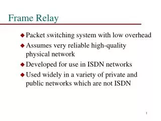
Introduction to Frame Relay • Eric Scace, an engineer at Sprint International, invented Frame Relay as a simpler version of the X.25 protocol to use across Integrated Services Digital Network (ISDN) interfaces. • Sprint first used StrataCom switches. • Cisco's acquisition of StrataCom in 1996 marked their entry into the carrier market. • Network providers commonly implement Frame Relay for voice and data as an encapsulation technique, used between LANs over a WAN. • Frame Relay has become one of the most extensively used WAN protocols, primarily because it is inexpensive compared to dedicated lines.
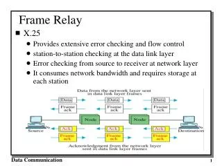
Conti… • Frame Relay handles volume and speed efficiently by combining the necessary functions of the data link and Network layers into one simple protocol. • As a data link protocol, Frame Relay provides access to a network, delimits and delivers frames in proper order, and recognizes transmission errors through a standard Cyclic Redundancy Check. • As a network protocol, Frame Relay provides multiple logical connections over a single physical circuit and allows the network to route data over those connections to its intended destinations.
Frame Relay Operation • The connection between a DTE device and a DCE device consists of both a Physical layer component and a link layer component: • The physical component defines the mechanical, electrical, functional, and procedural specifications for the connection between the devices. One of the most commonly used Physical layer interface specifications is the RS-232 (Recommended standard-for serial binary data signals from DTE DCE) specification. • The link layer component defines the protocol that establishes the connection between the DTE device, such as a router, and the DCE device, such as a switch. • POP -- Point-of-Presence (point of interconnection between the connection facility provided by the telephone company and the building main distribution facility) • FRAD -- Frame Relay access device
Virtual Circuits • The connection through a Frame Relay network between two DTEs is called a virtual circuit (VC). The circuits are virtual because there is no direct electrical connection from end to end. • There are two ways to establish VCs: • SVCs, switched virtual circuits, are established dynamically by sending signaling messages to the network (CALL SETUP, DATA TRANSFER, IDLE, CALL TERMINATION). • PVCs, permanent virtual circuits, are preconfigured by the carrier, and after they are set up, only operate in DATA TRANSFER and IDLE modes. • Note: Some publications refer to PVCs as private VCs.
Conti… • VCs provide a bidirectional communication path from one device to another. VCs are identified by DLCIs (data link connection identifier). • DLCI values typically are assigned by the Frame Relay service provider. Usually, DLCIs 0 to 15 and 1008 to 1023 are reserved for special purposes. Therefore, service providers typically assign DLCIs in the range of 16 to 1007. • Frame Relay DLCIs have local significance, which means that the values themselves are not unique in the Frame Relay WAN.
Conti… • Multiple VCs • Frame Relay is statistically multiplexed, meaning that it transmits only one frame at a time, but that many logical connections can co-exist on a single physical line. • The Frame Relay Access Device (FRAD) or router connected to the Frame Relay network may have multiple VCs connecting it to various endpoints. • Multiple VCs on a single physical line are distinguished because each VC has its own DLCI. • This capability often reduces the equipment and network complexity required to connect multiple devices, making it a very cost-effective replacement for a mesh of access lines
Conti… • Frame Relay uses virtual circuits to carry packets from one DTE to another
Standard Frame Relay Frame • Frame Relay takes data packets from a Network layer protocol, such as IP or IPX, encapsulates them as the data portion of a Frame Relay frame, and then passes the frame to the Physical layer for delivery on the wire. • The header and trailer are defined by the Link Access Procedure for Frame Relay (LAPF) Bearer Services specification, ITU Q.922-A. • DLCI • Extended Address ( value=1 mean last DLCI) • C/R (not generally used by Frame Relay) • Congestion Control Contains 3 bits :- • FECN ( Forward Explicit Congestion Notification) • BECN ( Backward Explicit Congestion Notification) • DE ( Discard Eligible)
Frame Relay Topology • You need to consider the topology from several perspectives to understand the network and the equipment used to build the network. • Complete topologies for design, implementation, operation, and maintenance • Star ( Hub and Spoke) Topology :- The simplest WAN topology is a star, • Full Mesh: A full mesh topology suits a situation in which the services to be accessed are geographically dispersed and highly reliable access to them is required.
Conti… • Partial Mesh Topology • For large networks, a full mesh topology is seldom affordable because the number of links required increases dramatically. • The issue is not with the cost of the hardware, but because there is a theoretical limit of less than 1,000 VCs per link. In practice, the limit is less than that. • For this reason, larger networks are generally configured in a partial mesh topology.
Conti… • Types of topologies that are used for implementing Frame Relay in different environments
Local Management Interface (LMI) • Need for DTEs to dynamically acquire information about the status of the network. • A consortium of Cisco, Digital Equipment Corporation (DEC), Northern Telecom, and StrataCom extended the Frame Relay protocol to provide additional capabilities for complex internetworking environments. These extensions are referred to collectively as the LMI. • Basically, the LMI is a keepalive mechanism that provides status information about Frame Relay connections between the router (DTE) and the Frame Relay switch (DCE). R1#show frame-relay lmi
Conti…. • The LMI type configured on the router must match the type used by the service provider. • If it is necessary to set the LMI type, use the frame-relay lmi-type [cisco | ansi | q933a] interface configuration command. • Configuring the LMI type, disables the autosense feature. • When manually setting up the LMI type, you must configure the keepalive interval on the Frame Relay interface to prevent status exchanges between the router and the switch from timing out. • You can change the keepalive interval with the keepalive interface configuration command. Default is 10s.
Configure a Basic Frame Relay PVC • Configure a static Frame Relay map (static)
Frame Relay Configuration • Step 1. Setting the IP Address on the Interface – ip address command • Step 2. Configuring Encapsulation – encapsulatin frame-relay [cisco | ietf ] command • Step 3. Setting the Bandwidth – bandwidth command • Step 4. Setting the LMI Type (optional) • Subinterface configuration (dynamic) R1(config-if)#interface serial 0/0/0.103 point-to-point. R1(config-subif)#frame-relay interface-dlci 103. • Configuring a Static Frame Relay Map • frame-relay map protocol protocol-address dlci [broadcast] • To Verify • Show frame-relay map
Configure an Advanced Frame Relay PVC • Steps to configure point-to-point subinterfaces on a physical interface (dynamic)
Advanced Concepts of Frame Relay Technology • The reachability issues associated with the Frame Relay NBMA topology
Solving Reachability issue • Frame Relay Subinterfaces • Frame Relay can partition a physical interface into multiple virtual interfaces called subinterfaces. • A subinterface is simply a logical interface that is directly associated with a physical interface. • Therefore, a Frame Relay subinterface can be configured for each of the PVCs coming into a physical serial interface. • Frame Relay subinterfaces can be configured in either point-to-point or multipoint mode: • Point-to-point A single point-to-point subinterface establishes one PVC connection to another physical interface or subinterface on a remote router on its own subnet, • Multipoint A single multipoint subinterface establishes multiple PVC connections to multiple physical interfaces or subinterfaces on remote routers in the same subnet.
Paying for Frame Relay • Key Terminologies • Access rate or port speed • From a customer's point of view, the service provider provides a serial connection or access link to the Frame Relay network over a leased line. The speed of the line is the access speed or port speed. • Committed Information Rate (CIR) • Customers negotiate CIRs with service providers for each PVC. The CIR is the amount of data that the network receives from the access circuit. • Oversubscription • Service providers sometimes sell more capacity than they have This can cause traffic issues, such as congestion and dropped traffic.
Conti… • Burst • A great advantage of Frame Relay is that any network capacity that is being unused is made available or shared with all customers, usually at no extra charge. • Bursting allows devices that temporarily need additional bandwidth to borrow it at no extra cost from other devices not using it. • Various terms are used to describe burst rates including the Committed Burst Information Rate (CBIR) and Excess Burst (BE) size.
Configure an Advanced Frame Relay PVC • Commands used for verifying Frame Relay operation • Show frame-relay pvc 102, show frame-relay map|lmi, • clear frame-relay inarp
Configure an Advanced Frame Relay PVC • Steps for troubleshooting a Frame Relay configuration
Summary • Frame relay is the most widely used WAN technology because it: • Provides greater bandwidth than leased line • Reduces cost because it uses less equipment • Easy to implement • Frame relay is associated with layer 2 of the OSI model and encapsulates data packets in a frame relay frame • Frame relay is configured on virtual circuits • These virtual circuits may be identified by a DLCI • Frame relay uses inverse ARP to map DLCI to IP addresses
Summary • Configuring frame relay requires • Enable frame relay encapsulation • Configuring either static or dynamic mapping • Considering split horizon problems that develop when multiple VCs are placed on a single physical interface • Factor affecting frame relay configuration • How service provider has their charging scheme set up • Frame relay flow control • DE • FECN • BECN
Summary • The following commands can be used to help verify frame relay configuration • Show interfaces • Show frame-relay lmi • Show frame-relay pvc ### • Show frame-relay map • Use the following command to help troubleshoot a frame relay configuration • Debug frame-relay lmi