FRAME RELAY
FRAME RELAY. by Erdem YILMAZ. What is Frame Relay?. high-performance WAN protocol operates at the physical and data link layers Originally designed for use across ISDN interfaces An example of packet-switched technology described as a streamlined version of X.25. Frame Relay vs. X.25.


FRAME RELAY
E N D
Presentation Transcript
FRAME RELAY by Erdem YILMAZ
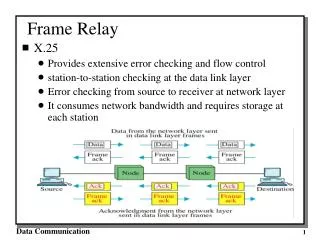
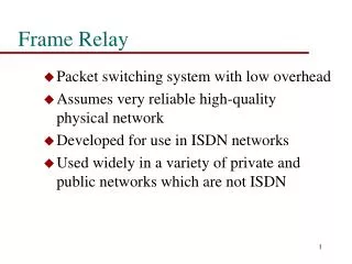
What is Frame Relay? • high-performance WAN protocol • operates at the physical and data link layers • Originally designed for use across ISDN interfaces • An example of packet-switched technology • described as a streamlined version of X.25
Frame Relay vs. X.25 • Frame Relay is a Layer 2 protocol suite, X.25 provides services at Layer 3 • Frame Relay offers higher performance and greater transmission efficiency than X.25
Frame Relay Devices • data terminal equipment (DTE) • terminating equipment for a specific network • typically are located on the premises of a customer • Examples: terminals, personal computers, routers, and bridges
Frame Relay Devices • data circuit-terminating equipment (DCE) • carrier-owned internetworking devices • to provide clocking and switching services in a network • actually transmit data through the WAN
Frame Relay Devices Figure 1 Frame Relay Devices
Frame Relay Virtual Circuits • provides connection-oriented data link layer communication • a logical connection between two data terminal equipment across a Frame Relay packet-switched network • provide a bi-directional communications path from one DTE device to another
Frame Relay Virtual Circuits • Switched virtual circuits (SVCs) • temporary connections requires sporadic data transfer between DTE devices across the Frame Relay network • Call Setup • Data Transfer • Idle • Call Termination
Frame Relay Virtual Circuits • Permanent Virtual Circuits (PVCs) • used for frequent and consistent data transfers between DTE devices across the Frame Relay network • Data Transfer • Idle
Congestion Control Mechanism • Forward-explicit congestion notification (FECN) • Backward-explicit congestion notification (BECN)
Forward-explicit congestion notification (FECN) • initiated when a DTE device sends Frame Relay frames into the network • When the framesreach the destination DTE device, the frameexperienced congestion in the path from source to destination • flow-control may be initiated, or the indication may be ignored
Backward-explicit congestion notification (BECN) • DCE devices set thevalue of the BECN bit to 1 in frames traveling in the opposite direction, informs the receiving DTE device that a particular path through the network iscongested • flow-control may be initiated, or the indication may be ignored
Frame Relay Discard Eligibility (DE) • (DE) bit is used to indicate that a frame has lower importance than otherframes • When the network becomes congested, DCEdevices will discardframes with the DE bit
Frame Relay Error Checking • common error-checking mechanism known as the cyclic redundancy check(CRC) • CRC compares two calculated values to determine whether errors occurred during thetransmission
Frame Relay Network Implementation • consists of a number of DTE devicesconnected toremote ports on multiplexer equipment via traditional point-to-point services
Frame Relay Network Implementation Figure 2 A simple Frame Relay network connects various devices to different servicesover a WAN.
Public Carrier-Provided Networks • Frame Relay switching equipment is locatedin the central offices of a telecommunications carrier • The DCE equipment also is owned by the telecommunications provider • The majority of today’s Frame Relay networks are public carrier-provided networks
Private Enterprise Networks • the administration and maintenance of the network are the responsibilitiesof the enterprise • All the equipment, including the switching equipment, isowned by the customer
Frame Relay Frames Figure 3 Frame Relay Frame
Frame Relay Frames • Flags indicate the beginning and end of the frame • Three primary components make up the FrameRelay frame • the header and address area • the user-data portion • the frame-check sequence(FCS)
Frame Relay Frames • The address area (2 bytes) • 10 bits represents the actualcircuit identifier • 6 bits of fields related to congestionmanagement
Frame Relay Frame Formats • Standard Frame Relay Frame • LMI Frame Format
Standard Frame Relay Frame • Flags • Delimits the beginning and end of the frame • The value of this field is always the same (7E or 01111110)
Standard Frame Relay Frame • Address – contains the following information • DLCI: The 10-bit DLCI is the essence of the Frame Relay header, values have local significance only, devices at opposite endscan usedifferent DLCI valuesfor the same virtual connection
Standard Frame Relay Frame • Address • Extended Address (EA):used to indicate whether the byte in which the EA valueis 1 is the last addressing field, the eighth bit of eachbyte of the Address field is used to indicate the EA
Standard Frame Relay Frame • Address • Congestion Control: consists of the three bits; FECN, BECN, and DE bits
Standard Frame Relay Frame • Data – Contains encapsulated upper-layer data • serves totransport the higher-layer protocol packet (PDU) through a Frame Relay network
Standard Frame Relay Frame • Frame Check Sequence • Ensures the integrity of transmitted data
LMI Frame Format Figure 4 Nine fields comprise the Frame Relay that conforms to the LMI format
LMI Frame Format • Flag - Delimits the beginning and end of the frame • LMI DLCI - Identifies the frame as an LMI frame instead of a basic Frame Relay frame • Unnumbered Information Indicator - Sets the poll/final bit to zero
LMI Frame Format • Protocol Discriminator - Always contains a value indicating that the frame is an LMI frame • Call Reference - Always contains zeros. This field currently is not used for any purpose • Message Type • Status-inquiry message: Allows a user device to inquire about the status of the network • Status message: Responds to status-inquiry messages. Status messages include keep-alivesand PVC status messages
LMI Frame Format • Information Elements—Contains a variable number of individual information elements (IEs) • IE Identifier: Uniquely identifies the IE • IE Length: Indicates the length of the IE • Data: Consists of one or more bytes containing encapsulated upper-layer data • Frame Check Sequence (FCS) - Ensures the integrity of transmitted data
Thanks For Listening Erdem YILMAZ