Download
1 / 28
340 likes | 698 Views
Frame Relay. Accessing the WAN – Chapter 3. Objectives. Describe the fundamental concepts of Frame Relay technology in terms of Enterprise WAN services including Frame Relay operation, Frame Relay implementation requirements, Frame Relay maps, and LMI operation.

E N D
Frame Relay Accessing the WAN– Chapter 3
Objectives • Describe the fundamental concepts of Frame Relay technology in terms of Enterprise WAN services including Frame Relay operation, Frame Relay implementation requirements, Frame Relay maps, and LMI operation. • Configure a basic Frame Relay PVC including configuring and troubleshooting Frame Relay on a router serial interface and configuring a static Frame Relay map. • Describe advanced concepts of Frame Relay technology in terms of Enterprise WAN services including Frame Relay sub-interfaces, Frame Relay bandwidth and flow control. • Configure an advanced Frame Relay PVC including solving reachability issues, configuring Frame Relay sub-interfaces, verifying and troubleshooting Frame Relay configuration.
Fundamental Concepts of Frame Relay Technology • Does not require dedicated circuits • Cost effective & Flexible • Uses concepts of private virtual circuits (PVC)
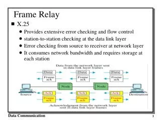
Frame Relay Operation • The DTE sends frame to the DCE Switch on the WAN edge • The frames move from switch to switch across the WAN to the destination DCE switch on the WAN edge • The destination DCE delivers the frames to the DTE
Virtual Circuits • The connection through a Frame Relay network between two DTEs is called a virtual circuit (VC) • The circuits are virtual because there is no direct electrical connection from end to end – logical connections
Data Link Connection Identifier (DLCI) • VCs are identified by DLCIs • DLCIs have local significance • DLCI has no significance beyond the single link
Multiple Virtual Circuits (VCs) • Frame Relay is statistically multiplexed • FR transmits only one frame at a time but many logical connections can co-exist on a single physical line • Multiple VCs on the same access link are distinguished by the local DLCI
Standard Frame Relay Frame Format • The CPE router encapsulates each Layer 3 packet inside a Frame Relay header and trailer before sending it across the VC • The header and trailer are defined by the Link Access Procedure for Frame Relay (LAPF) Bearer Services specification, ITU Q.922-A
Frame Relay Topologies • Star (Hub and Spoke) • Full Mesh • Partial Mesh
Frame Relay Address Mapping • Before a Cisco router is able to transmit data over Frame Relay, it needs to know which local DLCI maps to the Layer 3 address of the remote destination • Address-to-DLCI mapping can be accomplished either by static or dynamic mapping • The Inverse Address Resolution Protocol (ARP) obtains Layer-3 addresses of other stations from Layer-2 DLCI addresses • Whereas ARP translates Layer 3 addresses to Layer 2 addresses, Inverse ARP does the opposite
Frame Relay Address Mapping Dynamic Mapping • Relies on Inverse ARP to resolve a next hop network protocol address to a local DLCI value. • The Frame Relay router sends out Inverse ARP requests on its PVC to discover the protocol address of the remote device connected to the Frame Relay network. • The router uses the responses to populate an address-to-DLCI mapping table on the Frame Relay router or access server. • The router builds and maintains this mapping table, which contains all resolved Inverse ARP requests, including both dynamic and static mapping entries.
Frame Relay Address Mapping Static Mapping • One can override dynamic Inverse ARP mapping by supplying a manual static mapping for the next hop protocol address to a local DLCI • A static map works similarly to dynamic Inverse ARP by associating a specified next hop protocol address to a local Frame Relay DLCI • You cannot use Inverse ARP and a map statement for the same DLCI and protocol.
Local Management Interface • LMI is a keepalive mechanism that provides status information about Frame Relay connections between the router (DTE) and the Frame Relay switch (DCE) • LMI types configured on the router must match the type used by the service provider. Three types of LMIs are supported by Cisco routers: • Cisco - Original LMI extension • Ansi - Corresponding to the ANSI standard T1.617 Annex D • q933a - Corresponding to the ITU standard Q933 Annex A • LMI Extensions • VC status messages - Provide information about PVC integrity • Multicasting - Allows a sender to transmit a single frame that is delivered to multiple recipients. • Global addressing - Gives connection identifiers global rather than local significance • Simple flow control - Provides for an XON/XOFF flow control
Configuring a Basic Frame Relay Network Step 1. Setting the IP Address on the Interface Step 2: Configure Encapsulation Step 3: Setting the bandwidth Step 4: Set the LMI type (optional)
Solving Reachability Issues • Split Horizon – Updates received on the physical interface is not retransmitted out the same interface • Problem for NBMA, Hub-Spoke Networks
Advanced Frame Relay Topics Frame Relay Bursting
Summary • Frame relay is the most widely used WAN technology because it: • Provides greater bandwidth than leased line • Reduces cost because it uses less equipment • Easy to implement • Frame relay is associated with layer 2 of the OSI model and encapsulates data packets in a frame relay frame • Frame relay is configured on virtual circuits • These virtual circuits may be identified by a DLCI • Frame relay uses inverse ARP to map DLCI to IP addresses
Summary • Configuring frame relay requires • Enable frame relay encapsulation • Configuring either static or dynamic mapping • Considering split horizon problems that develop when multiple VCs are placed on a single physical interface • Factor affecting frame relay configuration • How service provider has their charging scheme set up • Frame relay flow control • DE • FECN • BECN
Summary • The following commands can be used to help verify frame relay configuration • Show interfaces • Show frame-relay lmi • Show frame-relay pvc ### • Show frame-relay map • Use the following command to help troubleshoot a frame relay configuration • Debug frame-relay lmi