Download
1 / 26
280 likes | 431 Views
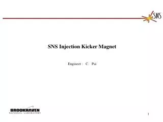
SNS Injection Kicker Magnet Engineer : C. Pai. Injection Kicker Location. Injection Kicker Location. Short Injection Kicker. Beam Direction. Long Injection Kicker. Long Kicker Assembly. Horizontal Kicker. Vertical Kicker. Long Kicker Set Assembly, one Vertical and one Horzontal.

E N D
SNS Injection Kicker Magnet Engineer : C. Pai
Injection Kicker Location Short Injection Kicker Beam Direction Long Injection Kicker
Long Kicker Assembly Horizontal Kicker Vertical Kicker
Kicker Magnet Module (Single Power Supply) Eddy Current Strip Clamp Spring Beam Pipe Ferrite Block Base Plate
Ceramic Chamber and magnet Support Sliding End Support Fixed End Support Chamber Flange
Displacement Plot Under Combined load: Weight and side acceleration ( 1 g in Z and .5 g in Y) .5 g in Y 1g in Z Max. Def.=.0082” in Y
Von Mises Stress Plot Under Combined load: Weight and axial acceleration( 1 g in Z+.5 g in X) .5 g in x 1 g in Z Max. Stress=2931 psi Allowable: Al-6061T6 6,000 psi (ASME-welded)
Fig. 15 Von Mises stress plot of stand under combined load: a. Own weight b. .5 g side acceleration c. .5 g axial acceleration Max. stress=3782 psi Allowable: 6061-T6 6,000 psi (ASME-welded)
Model for Water Cooling and Coil Temperature Analysis Power condition: RMS Power: 1100 w Current: 1230 amp. Frequency: 60 Hz. Epoxy Insulator k=.0029 w/cm/c Water channel,T=42oC h=.02837w/cm2/c (Convection coef.) Conductor k=4.01w/cm/c
Temperature rise of coil Thi:47.8 oC Temperature of Insulation At end of 10 minutes. Temperature of Copper conductor oC Troom42 oC Seconds
Temperature distribution afte 10 minutes T of conductor and water: 5.8oC T of conductor and insulation: .03oC Tmax: 47.829oC (Twater: 42 oC) Unit: oC
Maximum thermal stress: Unit:N/cm2 Max. stress, max=577.8N/cm2 or 837.4 psi Allowable of Epoxy bonding: 3000 psi
Injection kicker Model, long kicker Coil Ferrite
B-H Curve of CMD 5005 Ferrite Material: CMD 5005 Ni-Zn Ferrite Initial permeability: 1,600 Maximum permeability: 4,500 Maximum flux density: 3,000 gauss
Magnetic field, Bx plot at center cross section , z=0 , Long Magnet Center field Bo=784.9 gauss Current: 1,230 amp. Total store energy: 119.7 Joule Inductance: 158 x 10-6 H
Total integral field along center line Long Magnet gauss cm 1. Integral field at center: Bdl=65,850.9 gauss-cm 2. Average integral field at 16 cm radius , Bdl=65,65721.3 gauss-cm 3. Uniformity of integral field : 1% in 16 cm radius 4. Effect length: 83.9 cm
Fig. 8 Max. Magnetic field, Bmod in the edge cross section, z=64 Long Magnet Bmax=2,905Gauss at corner, less than 3,000 gauss