Injection
Injection. Injection. We going to have a lot to do at injection: Establish circulating beam Deal with multipoles Start tracking and correcting b1, b2 and b3 as persistent currents decay

Injection
E N D
Presentation Transcript
Injection • We going to have a lot to do at injection: • Establish circulating beam • Deal with multipoles • Start tracking and correcting b1, b2 and b3 as persistent currents decay • To keep energy constant the horizontal orbit correctors will be driven a la BFS. to compensate b1 drift. (via a knob) • Adjustment of TDI & injection collimators • Adjustment of cleaning insertion collimators • RF: Capture by 200 MHz, longitudinal feedback • RF: Transverse feedback • RF: Transfer from 200 to 400 MHz • Orbit, tune, chromaticity, energy etc... Concentrate here on actually getting beam safely into the ring
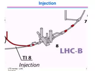
Last part of the lines Horizontal Vertical Horizontal Vertical Bends Septum TED Quad-pickup-corrector
TI8 SEPTA TED
LHC Ring 2 Common
Injection Volker Mertens MSI MKI TDI TCDD
Instrumentation Claude Fischer
Requirements • Energy • constant energy at SPS extraction • energy error needs to be measured on injected beam before capture. (50 MeV = 0.15 mm) B/B < 10-4 over all injections • Beam needs to be delivered to 1.5 with respect to closed orbit of which 0.5 is for kicker ripple • I.e approximately 0.7 mm at the septa • exceptionally good orthogonal steering • Batch-to-batch stability • vital to prevent excessive injection oscillation • Good matching - emittance preservation • a science in itself • run to run stability will be key
Requirements: TDI • Requires an orbit control within 0.5 sigma of the beam size at the TDI (-> 0.2mm). • The TDI must be accurately aligned to the vertical crossing angle orbit. • For the current crossing angle separation scheme (Version 6 of the LHC lattice) the vertical orbit changes by 0.2mm over the length of the TDI which is of the same magnitude as the required alignment accuracy. (5m long 200 kg each, precision:0.1 mm 0.2 s). 2 independent step motors
Requirements: Orbit • Separation at IP: orbit bumps • Separation at parasitic crossings: crossing angle • Compensation of spectrometer magnets • ALICE • spectrometer magnet off at injection • IP2: vertical crossing angle 210 rad • Possible need for orbit offset at MKI - additional 3 bump • Horizontal parallel separation bump • LHCb • spectrometer magnet on & it can change polarity • compensation produces large crossing angle in horizontal plane, combine with horizontal crossing angle bump • parallel vertical separation bump LHCb Expt Dipole MCBW IP8 MCXW MCBWB
Pilot I • Issue injection request: RF, kickers, BI • Retract TED at end of TI 8, move in TDI and send pilot pulse(s) onto TDI (kickers off), tune remaining part of line. • TDI out • Take PILOT into BLUE (or YELLOW) ring Side view Kicker TDI D1
Pilot II Establish Circulating Beam • If beam doesn't circulate - go to • Measure & correct: • transverse injection oscillations, injection error, Inject & dump if necessary • momentum error, re-do if necessary. • RF damper performance • RF LFB performance • Q, Q', • separation at IPs, crossing angle, spectrometer compensation bump • closed orbit. • Adjust TDI with respect to closed orbit • Coarse adjustment of collimators with respect to closed orbit: injection and cleaning 8.5 Injection collimators 20 down stream with respect to to TDI, other side of the IP
Intermediate beam Medium bunch intensity: any losses distributed • Prerequisites: • collimators to coarse, • TDI in, • possibly some auxiliary collimators (2 secondary betatron and 2 secondary momentum) • (tune, orbit etc…) • This mode makes use of increase sensitivity of BPMs with intensity and would allow: • exploration of the aperture • fine adjustment of TDI & optics check • fine adjustment of collimators • and checking of other beam instrumentation such as BLMs
Dense Now it gets serious… should be ready to take 12 high intensity batches into each ring • If TI 2/8 drift during injection (auto-)re-steer final TI 2/8 elements • Prerequisites: • All collimators in at specified positions. n1 = 6-7, n2 = 7-8 sigma. Positions with respect to average closed orbit. • Ionization monitors operational • Local orbit feedback to preserve optimum protection • BLMs • While all this going on: • b1, b3 correction, • Q-loop (pilot, intermediate & dense???) • & orbit feedback (only when there’s beam…)
Interlocks etc... Frightening • Interlocks • Before the injection of a full batch one must ensure that all magnets in the transfer line and the LHC machine have their proper settings. If some magnets are not correctly set part of the injected beam can reach either the cold elements of the machine or some parts of the detectors. • Here one must keep in mind that the transfer lines use pulsed magnets and ensuring a proper setting of all the magnets requires a well defined checklist and interlock system. • Lock controls • In the case of a full batch injection operation errors at the MKI and MSI elements can lead to hardware damage in the LHC machine. Thus, when changing from the pilot bunch injection mode to the full batch injection changes to the injection settings (this includes orbit changes at the TDI) must be excluded by an interlock system.
Controls & Instrumentation • Calculate and steer angle and position of beam using BPMs and elements in transfer line. • Need accurate measurement of optics in lines to calculate x, x’, y, y’ • manual and automatic steering • Display of injection screens, record profiles & positions • Fixed displays of transfer lines • bunch currents, beam sizes, beam loses, beam position • logging of everything • Bunch intensities as delivered by SPS per batch, along the batch • Synchronisation • intensity selection, bunch configuration selection, ring selection & variations (inject at head or tail of circulating beam), diagnostics
Control II • Trajectory measurement & correction • threading, injection errors, energy mismatch, injection oscillations, • batch to batch variations • Matching • lines & LHC as one, OTR screens… etc. • Collimator control • injection & cleaning, precise, accurate, with respect to closed orbit, need knowledge of optics & emittance • Closed orbit control • lock orbit • collimators • kickers & septa • TDI • crossing angle • parallel separation bumps
Controls III • Septa & Kicker control • timing, view kick etc.. automatic & manual • TDI control • in terms of beam size, wrt to closed orbit • TCDD • in & out • RF: • Mountain range display, analog signals from pickups at end of lines, • Waveform acquisition: phase loop, injection transient signals. • control of phase, frequency, voltage etc. • Clearly, as usual, settings management, logging, post mortem, on-line model...
Conclusions • Precise and accurate control of injection process is mandatory • Instrumentation and controls must be reliable • Good diagnostics, good understanding and sophisticated control facilities will be required • bunch selection & the transfer process • monitoring and steering of the end of the lines • orbit control throughout the IP2 and IP8 • matching • Needless to say interlocks are vital • Sector test will be less demanding but will provide a good opportunity to test many features.