Effective Palletizing: Using the FRAME Program Instruction
150 likes | 183 Views
Understand how the FRAME instruction streamlines palletizing tasks for robots not aligned with X and Y axes. Learn the syntax, parameters, and examples of the FRAME program for precise orientation definition. Optimize palletizing processes with this comprehensive guide.

Effective Palletizing: Using the FRAME Program Instruction
E N D
Presentation Transcript
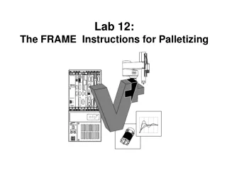
Lab 12: The FRAME Instructions for Palletizing
Lab 12: Relative Moves (Palletizing) What if the pallet is not in line with the X and Y Axis?
Z 1 2 3 Y A B C D The FRAME Program Instruction (Continued) What happens if the pallet is off the X and Y Axis?
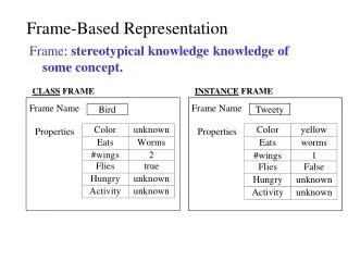
Z 1 2 3 Y A B C D The FRAME Program Instruction (Continued) While the robot can be used to define an X, Y, Z position very accurately, it is often difficult to define precisely an orientation. For applications such as palletizing, the FRAME function is very useful for accurately defining a base transformation whose position and orientation are determined by four positions.
Z 1 2 3 Y A B C D The FRAME Program Instruction (Continued) The FRAME instruction makes it possible to palletize when and if the pallet is not lined up with the X and Y axis of the robot. It is often difficult to have the pallet stop and line up with the exact X-Y axis of the robot each time. It also requires that the robot and conveyor must be aligned physically perfect which is also difficult. Using the FRAME instruction three points are taught to identify three corners of a frame. Once three points are taught the X and Y axis angles are defined.
The FRAME Program Instruction In addition, using the FRAME instruction allows the use of a vision system to teach the three points of the FRAME with other locations being relative.
The FRAME Program Instruction Function Return a transformation value defined by four positions. Syntax FRAME (location_1, location_2, location_3, location_4)
Parameters location_1 Transformation, compound transformation, or a transformation-valued function whose position is used to define the X axis of the computed frame. location_2 Transformation, compound transformation, or a transformation-valued function whose position is used to define the X axis of the computed frame. location_3 Transformation, compound transformation, or a transformation-valued function whose position is used to define the Y axis of the computed frame. location_4 Transformation, compound transformation, or a transformation-valued function whose position is returned as the position of the computed frame transformation.
The FRAME Program Instruction 1. Its origin is at the point defined by location_4. 2. Its positive X axis is parallel to the line passing through the points defined by location_1 and location_2, in the direction from location_1 to location_2. 3. Its X-Y plane is parallel to the plane that contains the points defined by location_1, location_2, and location_3. 4. Its positive Y direction is from the computed X axes (as defined above), toward the point defined by location_3.
The FRAME Program Instruction Example The following instruction defines the transformation base.frame to have the same X, Y, Z position as origin, its X axis parallel to the line from center to x, and its Y axis approximately in the same direction as the line from center to y. SET base.frame = FRAME(center, x, y, origin)
X - Y Y -X The FRAME Program Instruction Example Program: Pallet 3x 4 (12 locations)
The FRAME Program Instruction Example Program: Pallet 3x 4 (12 locations) Teach Absolute Moves: X, Y, Z, & Roll LOC1 corner of pallet LOC2 in X direction LOC3 in Y direction LOC1 Orientation Variables: M size of pallet block Pallet1 name for pallet
The FRAME Program Instruction Example Program: Pallet 3x 4 (12 locations) M = 63.5 ; block size x 2 - size of each box + one space H = 70 ; 70 mm above pallet - used for approach and depart MOVE #Safe MOVE abovesafe Set Pallet = frame (LOC1, LOC 2, LOC3, LOC 1) ;name for pallet with LOC1 as the orientation SET NewLoc = Pallet For column = 1 to 3 ;loop for number of columns For row = 1 to 4 ;loop for number of rows Call PICK ( ) ;pick up block at same place each time Call PLACE ( ) ;uses NewLoc variable in PLACE sub SET NewLoc = NewLoc: TRANS( , M) ;skip X, add M to Y axis - row End ; for row SET NewLoc = NewLoc:TRANS (-M, (-4*M) ) ;move back to the left for next row End ; for Column ;end of outside for loop .End ;end of program
Z 1 2 3 Y A B C D The FRAME Lab Assignment Develop a palletizing program as shown below with the pallet not square to the X-Y axis. Teach the location for part 1A , 4A, 4F and Center. Use the FRAME instruction for computing the rest of the relative locations. Modify the palletizing program from lab 11 adding the FRAME instruction for transforming the locations of the pallet program.
Lab 12: The FRAME Instructions for Palletizing The End