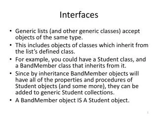
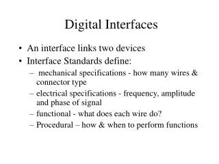
Digital Interfaces
Digital Interfaces. An interface links two devices Interface Standards define: mechanical specifications - how many wires & connector type electrical specifications - frequency, amplitude and phase of signal functional - what does each wire do? Procedural – how & when to perform functions.

Digital Interfaces
E N D
Presentation Transcript
Digital Interfaces • An interface links two devices • Interface Standards define: • mechanical specifications - how many wires & connector type • electrical specifications - frequency, amplitude and phase of signal • functional - what does each wire do? • Procedural – how & when to perform functions
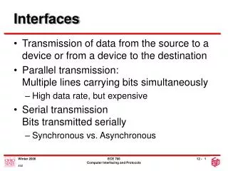
Serial vs. Parallel • In serial transmission one bit is sent with each clock pulse. • Two types of serial transmission: • asynchronous • synchronous • In parallel transmission multiple bits are sent with each clock pulse. Faster/more expensive upated 1/2002
Serial Transmission 0 1 1 0 0 0 1 0
Parallel Transmission 01100010 01100010
Serial Transmission • Asynchronous & Synchronous • Concerned with timing issues • How does the receiver know when the bit period begins and ends? • Small timing difference become more significant over time if no synchronization takes place between sender and receiver
Serial communication Data transmitted 1 character at a time Character format is 1 start & 1 or more stop bits, plus data of 5-8 bits Character may include parity bit Timing needed only within each character Resynchronization each start bit Uses simple, cheap technology Wastes 20-30% of bandwidth Asynchronous Transmission
Asynchronous Transmission START BIT STOP BIT 0 1 1 0 0 0 1 0 0 1 1 0 0 0 1 0 0 1 1 0 0 0 1 0 Gaps of indeterminate size
Serial communication Large blocks of bits transmitted without start/stop codes Synchronized by clock signal or clocking data Data framed by preamble/post amble bit patterns More efficient than asynchronous Overhead typically below 5% Used at higher speeds than asynchronous Synchronous Transmission
Synchronous Transmission 0 1 1 0 0 0 1 0 0 1 1 0 0 0 1 0 0 1 1 0 0 0 1 0 0 1 1 0 0 0 1 0 0 0 1 0
Synchronization Choices • Low-speed terminals and PCs commonly use asynchronous transmission • inexpensive • “burst” tendency of communication reduces impact of inefficiency • Large systems and networks commonly use synchronous transmission • overhead too expensive; efficiency necessary • error-checking more important
Generic Communications Interface Illustration DTE DTE DCE DCE (Network) Converts totransmissionmedia/ converts to generated data Generates Data Converts totransmissionmedia/ converts to generated data ReceivesData
EIA’s “Recommended Standard” (RS) Specifies mechanical, electrical, functional, and procedural aspects of the interface Used for connections between DTEs and voice-grade modems, and many other applications RS-232C (EIA 232C)
25-pin connector with a specific arrangement of leads DTE devices usually have male DB25 connectors while DCE devices have female In practice, fewer than 25 wires are generally used in applications Mechanical Specifications
DB-25 Female DB-25 Male RS-232 DB-25 Connectors
Limited RS-232 RS-232 DB-9 Connectors
Specifies signaling between DTE and DCE Uses NRZ-L encoding Voltage -15V to -3V = binary 1 Voltage +15V to +3V = binary 0 Rated for < 20Kbps and < 15Mts greater distances and rates are theoretically possible, but not necessarily wise Electrical Specifications
Specifies the role of the individual circuits Data circuits in both directions allow full-duplex communication Timing signals allow for synchronous transmission (although asynchronous transmission is more common) Functional Specification
Multiple procedures are specified Provides means of attachment between computer and modem Specifies method of transmitting data between devices Specifies method of cooperation for exchange of data between devices Handshaking between the two equipment Procedural Specification
SG SG DTR DTR DSR DSR RTS RTS CTS CTS CD CD TD TD RD RD Null Modem Cable • Allows DTE to DTE direct communication
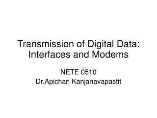
Modems • Modulator - converts digital signal to analog signal • Demodulator - converts analog signal to digital signal upated 1/2002
Data Rate • Encoding Technique • Physical properties of medium • Can increase speed by increasing frequency but every line has upper and lower limits • frequency range = bandwidth upated 1/2002
Bit Rate Summary upated 1/2002