Download
1 / 66
670 likes | 739 Views
Learn about Local Area Network (LAN) transmission media including bus, ring, and star topologies. Understand how these topologies work, their advantages, and disadvantages. Explore the considerations for choosing transmission media in LAN setups.

E N D
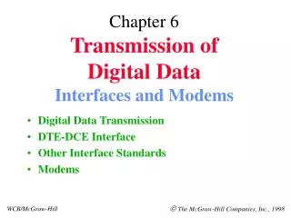
TRANSMISSION OF DIGITAL DATA INTERFACES AND MODEMS Alpesh Desai SDE RTTC Ahmedabad
OBJECTIVES • CONCEPT OF LAN • TRANSMISSION MEDIA FOR LAN • MEDIA ACCESS CONTROL • CARRIER SENSE MULTIPLE ACCESS (CSMA) • MEDIA ACCESS CONTROL-RING TOPOLOGY
INTRODUCTION • Network • A network is defined as an interconnected collection of computers. • Topology • The way in which the end systems or stations are interconnected.
LOCAL AREA NETWORK (LAN) • Speed 4, 10, 16 up to 100MBPS • Distance Few KMs (Typically 1.5KMs) • Requires dedicated local wiring (Ethernet, Token Ring, FDDI, ATM) • Shared access to medium
Requirements of topologies are: • Flexible to accommodate • Changes in physical location of the stations • Increase in number of stations. • Increase in LAN coverage. • Consistent with the media access method • Minimum cost of physical media.
STATION C STATION B STATIONA STATION E STATION D BUS HEADEND Bus Topology
Bus Topology • All stations share this medium for transmission to any other station. • Every stations listens to all the transmissions on the bus. • Every transmission has source and destination address so that stations can pick the messages meant for them and identify their senders
Bus Topology • Each station injects its signals on the bus, which flow in both the directions. • To avoid signal reflection at the ends of the bus, the bus is terminated by appropriate impedance called head end. • Signal flow is bi-directional. • Repeaters which interconnect two buses are used for extending the physical coverage of the network.
Advantages : • Stations are connected to the bus using a passive tap. • Least amount of media is used. • Coverage can be increased by extending the bus using repeaters. • New stations are easily added by tapping working bus.
Disadvantages : • Fault diagnostics is difficult • Fault isolation is difficult • Nodes must be intelligent
B C A RING D E RIU Ring Topology
Ring Topology • A ring network consists of a number of transmission links joined together in form of a ring through repeaters called Ring interface Units (RIU). • The transmission is usually unidirectional. • Each repeater receives the signals at its input and after regeneration, sends it to the repeater of the next station. • If the frame belongs to the station, a copy of the incoming frame is retained. Each frame contains source and destination addresses.
Ring Topology • Signals on the ring never reach an end. • They will keep circulating in the ring unless removed. • This responsibility is given to the source. • Possibility of source going down after transmitting a frame cannot be ruled out. Therefore a monitoring station is required to remove continuously circulating frames.
Ring Topology • To add a station means breaking the ring and adding an RIU. • RIU may fail resulting in total network failure. • A “Dead Man Relay” is usually provided to bypass a failed RIU. • Wire centers are provided to improve flexibility of removing or adding a station and to isolate a faulty section.
Advantages : • Short cable length • Suitable for optical fiber
Disadvantages : • Node failure cause network failure • Difficult to diagnose fault • Network reconfiguration is difficult
B A C CENTRAL CONTROLLER F D E Star Topology
Star Topology • A star network consists of dedicated links from the stations to the central controller. • Each interconnection supports two-way communication. • The central controller acts as a switch to route the frames from source to the destination
Advantages : • Control/fault diagnostics is centralized. • Simple access protocols are employed. • Ease of service • One device per connection
Disadvantages : • Single point of failure. • No sharing of transmission • Long cable lengths involved • Difficult to expand • Central node dependency
TRANSMISSION MEDIA FOR LAN • In a LAN, stations are interconnected using transmission media which can be a twisted pair, cable or a coaxial cable or even an optical fiber cable. • Choice of transmission media depends on data rate, cost , physical and electrical characteristics of the media , noise immunity, geographical coverage etc. • Popular physical transmission media are twisted pair, base-band and broadband coaxial cables and optical fibers.
Considerations for Choice of Transmission Media • Bandwidth • Connectivity • Geographic Coverage • Noise immunity • Security • Cost
Bandwidth • Bandwidth of the transmission media determines the maximum data rates which can be handled by the media Data rates are. • The bandwidth of transmission media is function of the length of the media e.g. it may be possible to achieve very high data rates on a low cost twisted pair but then maximum length of one transmission segment is limited to not more than a few meters.
Connectivity • Some transmission media are suitable for broadcast mode of operation and point to multi-point links, while others are better suited for point to point links. • For example, Optical fiber is suited for point to point links only. • Hub for point to multi point.
Geographic Coverage • In a LAN on a bus, the electrical signals should reach from one end to the other without degradation in quality of the signals below the required limits. • Attenuation and group delay characteristics of the medium determine overall distortion in the signals. • These characteristics are function of distance and therefore determine the geographic coverage of the LAN. • Propagation time, which is also dependent on the media characteristics, is an important consideration in that access mechanism where propagation delay determines the length of one segment of the media.
Noise immunity • Ideally the transmission media chosen for LAN should be free from interference from outside sources practically it is not possible. • Degree of immunity to interference varies from media to media. • Susceptibility to interference is because LAN cabling is usually done in the same ducts which carry power cables also. • Degree of noise immunity required depends on environment where a LAN is installed.
Security • In some of the LAN topologies and access methods it is very easy to tap on the LAN & pick up the messages without generating any alarm. For considerations of data security, the transmission medium is to be so chosen that it may not be easily tapped.
Cost • At present state of technology, cost of different media is different and is changing continuously. • Metallic media is becoming costlier and optical fiber costs are going down. • Cost of media is also related to the cost of equipment associated with the media. • Therefore an overall view of cost structure is more important than media alone.
Types of Twisted Pair • A twisted pair consists of two insulated wires twisted together in a spiral form (Fig.5a). • Twisting reduces cross talk and interference problems. • More than one pair can be bundled together in form of a cable (Fig.5b). • A twisted pair can also have a metallic braid as a shield (Fig.5c) to protect against noise.
TWISTED PAIR CABLE • Twisted pair is used for point to point, and point to multi-point applications. • As multi-point media, it supports fewer stations and over smaller distances than coaxial cable. • Tapping into twisted pair for additional stations is not so straight forward without disturbing other users or without changing transmission characteristics of the media. • Cost wise twisted pair is less expensive than coaxial cable or optical fiber.
COAXIAL CABLE • Coaxial cable is widely used as transmission medium in local area networks. • It consists of a central conductor, which can be solid or stranded, and an outer surrounding conductor. • The outer conductor can be solid or a braid. A solid dielectric material separates the two conductors. • If no dielectric material is used spacers are provided to hold the conductors in place. • Coaxial cable has very low loss, high bandwidth and very low susceptibility to external noise and cross talk.
COAXIAL CABLE • 50 Ohm & 75 Ohm CATV coaxial cables are popular in local area networks. • These impedance’s refer to characteristic impedance of the cable. • 50 Ohm cable is called base band cable because digital signals are transmitted without any modulation. • The outer conductor is metallic braid in 50 Ohm cable. Digital signals up to 10Mbps can easily be transmitted on base-band cable.
COAXIAL CABLE • 75 Ohm cable is broadband cable as it has bandwidth around 400MHz. It has solid outer conductor. Digital signals are transmitted on this cable on modulated carrier. • Unlike base-band, broadband cable is unidirectional. • Bi-directional connectivity is achieved by dividing the frequency band into inbound and outbound frequency bands.
COAXIAL CABLE • Coaxial cables can be used both for point to point and point to multipoint applications. When used as a bus, 50 Ohm cable can support of order of 100 devices per segment, the maximum length of a segment being 500 meters. • For distances more than five hundred meters, repeaters are required.
COAXIAL CABLE • 75 Ohm broadband cable can support about 1000 taps over a length of about 4 km. When used as bus, the coaxial cable can be easily tapped to add a new station.
Fibers are of three types • Step index, multi-made. • Step index, mono-mode. • Graded index fiber.
Characteristics of OFC. • Greater bandwidth • Smaller size and lighter • Greater repeater spacing due to low loss • High immunity to electromagnetic interference • Secure communication.
MEDIA ACCESS CONTROL • Access Centrally Controlled • Media is controlled by a central controller. • Distributed Access Control • Media is shared. • There is no single controller for the shared media. • In local area networks, distributed access control methods are more common.
Media Access Control – Bus Topology • The bus operates in broadcast mode, i.e. all the stations are always listening to all the transmissions on the bus. • Access control mechanisms are so designed that transmissions from different stations do not intermingle and all the stations get fair chance to transmit. • There are two techniques : • Token passing and CSMA/CD.
Token Passing • In token passing method, the stations connected on a bus are arranged in a logical ring i.e. the addresses of the stations are assigned a logical sequence with the last number of the sequence followed by the first. Each station knows identity of the stations proceeding and following it.
Token Passing • Access to the interconnecting bus is regulated by a control frame known as token. At a time only one station which holds the token has right to transmit its frame on the bus.
Token Passing • On the bus all the stations operate in broadcast mode so that every station can hear every transmission. When a station detects a token on the bus with its address, it transmits its data frame(s) each containing the source and destination addresses (Fig. 10). In the end, it transmits the token with address of the next station in the logical ring. Thus, in one cycle each station gets an opportunity to transmit.
Token Passing • To maintain continuity of communication, it is necessary that when turn comes each station transmits the token frame even if there is no data to send. The transmission sequence can get disrupted if a station is down. To account for such eventuality, a timer is provided. Station holding the token must release the token before time out else next station takes over and deletes the station from the logical ring for future transmissions.