Download
1 / 22
350 likes | 1.29k Views
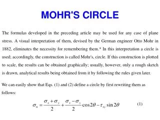
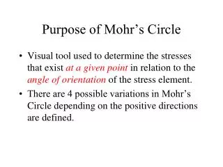
Purpose of Mohr’s Circle. Visual tool used to determine the stresses that exist at a given point in relation to the angle of orientation of the stress element. There are 4 possible variations in Mohr’s Circle depending on the positive directions are defined. . Sample Problem. y.

E N D
Purpose of Mohr’s Circle • Visual tool used to determine the stresses that exist at agiven point in relation to the angle of orientation of the stress element. • There are 4 possible variations in Mohr’s Circle depending on the positive directions are defined.
Sample Problem y A particular point on the part x sy = -2 ksi Some Part sx = 6 ksi txy = 3 ksi x & y orientation
x-axis (6 ksi, 3 ksi) 2 6 3 Center of Mohr’s Circle 3 (-2 ksi, -3 ksi) y-axis Mohr’s Circle t(CW) sy = -2 ksi sx = 6 ksi txy = 3 ksi s
(savg, tmax) Mohr’s Circle t(CW) sy = -2 ksi x-face sx = 6 ksi (6 ksi, 3ksi) txy = 3 ksi s s2 s1 savg= 2ksi (-2 ksi, -3ksi) y-face (savg, tmin)
(savg, tmax) (2 ksi, 5 ksi) Mohr’s Circle t(CW) sy = -2 ksi x-face sx = 6 ksi (6 ksi, 3ksi) R 3 ksi txy = 3 ksi s s2 s1 4 ksi y-face (savg, tmin) (2 ksi, -5 ksi) s1 = savg + R = 7 ksi s2 = savg – R = -3 ksi
(savg, tmax) (2 ksi, 5 ksi) Mohr’s Circle t(CW) sy = -2 ksi x-face sx = 6 ksi (6 ksi, 3ksi) 3 ksi 2q txy = 3 ksi s s2 s1 4 ksi y-face (savg, tmin) (2 ksi, -5 ksi)
(savg, tmax) (2 ksi, 5 ksi) Principle Stress t(CW) s2 = -3 ksi x-face (6 ksi, 3ksi) q = 18.435° 3 ksi 2q s1 = 7 ksi s s2 s1 Principle Stress Element 4 ksi Rotation on element is half of the rotation from the circle in same direction from x-axis (savg, tmin) (2 ksi, -5 ksi)
(savg, tmax) (2 ksi, 5 ksi) Shear Stress t(CW) x-face savg = 2 ksi f = 26.565° (6 ksi, 3ksi) 2f tmax = 5 ksi 3 ksi 2q s savg = 2 ksi s2 s1 Maximum Shear Stress Element 4 ksi y-face (savg, tmin) (2 ksi, -5 ksi)
Relationship Between Elements savg = 2 ksi tmax = 5 ksi sy = -2 ksi savg = 2 ksi f = 26.565° sx = 6 ksi q = 18.435° s2 = -3 ksi txy = 3 ksi s1 = 7 ksi q + f = 18.435 ° + 26.565 ° = 45 °
What’s the stress at angle of 15° CCW from the x-axis? y A particular point on the part V x s = ? ksi Some Part U s = ? ksi 15° x t = ? ksi U & V new axes @ 15° from x-axis
(savg, tmax) Rotation on Mohr’s Circle t(CW) (sU, tU) x-face 30° s s2 s1 savg= 2ksi y-face 15° on part and element is 30° on Mohr’s Circle (sV, tV) (savg, tmin)
(savg, tmax) Rotation on Mohr’s Circle t(CW) (sU, tU) x-face R sU = savg + R*cos(66.869°) sU = 3.96 ksi sV = savg– R*cos(66.869°) sV = 0.036 ksi tUV = R*sin(66.869°) tUV = 4.60 ksi 66.869° s s2 s1 savg= 2ksi y-face (sV, tV) (savg, tmin)
What’s the stress at angle of 15° CCW from the x-axis? y A particular point on the part V x sV= .036 ksi sU = 3.96 ksi Some Part U 15° x t = 4.60 ksi
Questions? Next: Special Cases
Special Case – Both Principle Stresses Have the Same Sign Y X Z Cylindrical Pressure Vessel
Mohr’s Circle sy t(CW) sx s sy sx This isn’t the whole story however… Mohr’s Circle for X-Y Planes sx = s1 and sy = s2
sz = 0 Mohr’s Circle sy t(CW) sx tmax = txz sx sz sz = 0 since it is perpendicular to the free face of the element. sz = s3 and sx = s1 s s1 s3 Mohr’s Circle for X-Z Planes
Mohr’s Circle sy t(CW) tmax = txz sx sz s s2 s1 s3 sz = 0 since it is perpendicular to the free face of the element. s1 > s2 > s3
Pure Uniaxial Tension sy = 0 sx = P/A s1= sx s2 = 0 Note when sx = Sy, Sys = Sy/2 Ductile Materials Tend to Fail in SHEAR
Pure Uniaxial Compression sy = 0 sx = P/A s1 = 0 s2= sx
Pure Torsion T T s2 = -txy s1 = txy Brittle materials tend to fail in TENSION. s1 CHALK
Uniaxial Tension & Torsional Shear Stresses • Rotating shaft with axial load. • Basis for design of shafts. (sx,txy) sx = P/A sx/2 s2 = sx/2-R s1 = sx/2+R txy = Tc/J (0,tyx)