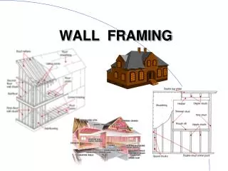
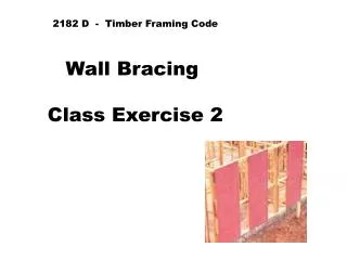
Timber Wall Framing Class Exercise 2
Timber Wall Framing Class Exercise 2. Reference Material. A.S. 1684.2 (2006) Non Cyclonic. Details:. Floor Plan – Same as Roofing Class Exercise 2 . Brick Veneer Construction . Roof Pitch 18 0. Cement Tile Roofing 60Kg/m 2. Eaves Width 600mm .


Timber Wall Framing Class Exercise 2
E N D
Presentation Transcript
Timber Wall Framing Class Exercise 2
Reference Material A.S. 1684.2 (2006) Non Cyclonic
Details: • Floor Plan – Same as Roofing Class Exercise 2 • Brick Veneer Construction • Roof Pitch 180 • Cement Tile Roofing 60Kg/m2 • Eaves Width 600mm • Floor to Ceiling Height 2.700m • Wall Framing – Seasoned Softwood MGP 15 • Concrete Raft Floor Slab • Wind Classification – N3
Wall Frame.(Supporting Conventional Roof Framing) Determine the most economical size, span & spacing of the following members • Bottom Wall plate – not trenched. • Top Wall plate – not trenched (to support rafters @ 600mm c/c) • Common Studs at 600mm c/c (not notched for erection bracing) • Noggings • Jamb Studs (studs at sides of openings) • Lintels • Eaves Beams (Verandah Beams) • Tie down spacing 1.800
Use Preliminary Calculations from Roofing exercise 2. • Summary • RLW Rafter = 2.064 say 2.100 • RLW Eaves = 0.788 • Purlin Set out = 1.872 • Half spread fan strut = 0.671 • Fan Strut Length = 0.931
Same as Roofing Class Exercise 2 Floor Plan
1. Fill in General Information from Prelim. Calcs & Specification S/softwood MGP 15 6 - N3 B1.1 60Kg/m Brick veneer 2.700m For roof mass use Table B1.1 p.219 Check Preliminary Calcs for rafter RLW & Eaves RLW
Calculate Eaves Overhang – Eaves RLW TL O/Hang = 0.600 + 0.150 COS 18 = 0.693m 0.788m RLW Eaves = 0.788m 0.150 0.600
S/softwood MGP 15 6 - N3 B1.1 60Kg/m Brick veneer 2.700m 0.788m Eaves RLW from preliminary calcs. = 0.788m
Calculate Common Rafter Span - RLW 2.064 4.127 2.064 Span = 4.127 2 = 2.064m RLW = Span + Overhang 2.064m + .788 = 2.852 S ay 3.000
S/softwood MGP 15 6 - N3 B1.1 10Kg/m Brick veneer 2.700m 0.788m 3.000m
2. Find information for Common Studs (rules & supp. Table) 2.700 6.2.1.2 0.600 90 x 35 6.3.2.1 Not notched 0.600m 7 Fill in Comments Column Refer page 59, rule 6.2.1.2 (Building Practice) Common Studs. Refer page 66, rule 6.3.2.1 (Member Sizes) Common Studs. Refer Supp. 6, Table 7 Common Studs – Single Storey not notched, 600mm c/c, Tile roof, 2.700m Height, 0.600m Rafter spacing, RLW of 3000 Select stud size - 90 x 35 (from table 7) Plan shows 100mm wide walls – will use 90 x 35 as per A.S. 1684.2 Table 7
3. Find information for Noggings (rules & supp. Table) 6.2.1.5 Refer page 62, rule 6.2.1.5 (Building Practice) Noggings. Check spacing requirements
Wall studs shall have continuous rows of noggings at 1350 mm maximum centres (see Figure 6.6). • Noggings are not required to be stress graded. • Nogging thickness shall be a minimum of 25 mm and shall be suitable for the proper fixing of cladding and linings. • Noggings shall be installed either centrally in the depth of the studs or flush with one face of the stud in order to provide fixing or support to cladding or linings. Stagger in the row of noggings shall not be greater than twice the nogging breadth.
3. Find information for Noggings (rules & supp. Table) 1.350m 6.2.1.5 90 x 35 Refer page 62, rule 6.2.1.5 (Building Practice) Noggings. Check spacing requirements Spacing of noggings = 1.350m max. Size for Noggings = same as for common studs, 90 x 35
information for Studs at sides of Openings (Rules & Supp. Table No.) 6.2.1.2 6.3.2.3 11 Refer page 59, rule 6.2.1.2 (Building Practice) Common Studs. Refer page 68, rule 6.3.2.3 (Member sizes) Jamb Studs. Refer Supp. 6, Table 11 Jamb Studs – Tile Roof Refer to window schedule for Opening Widths
Window Schedule: Window W W7 Bedroom 1 0.970 W8 Bedroom 1 0.530 W12 Bedroom 2 1.690 W13 Bedroom 3 1.690 W3 Bath 0.970 W2 WC 0.850 W1 Laundry 0.970 W4 Kitchen 1.930 W10 Dining 2.330 W9 Lounge 2.770 W11-D6 Family 3.610 W6 Ensuite 0.970 W14-D15 W/shop 2.530 D1 Entry 0.900
0.970 6.2.1.2 0.530 1.690 6.3.2.3 1.690 0.970 11 0.850 0.970 1.930 2.330 2.770 3.610 0.970 2.530 0.900 Fill in Opening Width information Go to Table 11 of supplements to size studs to suit opening widths
Table 11, supp.6 MGP 15 2006 RLW (3.000) Tile Roof Use Column
2006 Jamb Studs for W7 Will be 90 x 35 Each side of opening W7 Bedroom 1 Width = 0.970 Height = 2.700 Go back & fill in Stud sizes for other openings
6.2.1.2 2/90 x35 0.970 90 x 35 0.530 1.690 6.3.2.3 2/90 x 35 2/90 x 35 1.690 2/90 x 35 0.970 11 0.850 90 x 35 2/90 x 35 0.970 1.930 2/90 x 35 2.330 2/90 x 35 2.770 2/90 x 35 3.610 2/90 x 45 0.970 2/90 x 35 2/90 x 35 2.530 90 x 35 0.900 Window 7 – studs at sides of openings = 2/90 x 35 Fill in remaining stud information using Table 11. Next – Size Top & Bottom Plates
5. Find information for Top Plates (Rules & Supp. Table No.) 6.2.2.1 Single storey Tie Roof 3.000m 6.3.4 16 1.800m Fill in Comments Column Refer page 62, rule 6.2.2.1 (Building Practice) Plates General. Refer page 73, rule 6.3.4 (Member Sizes) Top Plates. Refer Supp. 6, Table 16 Top Plates (Tile Roof – Single or Upper Storey). Check Table 16 for size of Top Plates
2006 Rafter Spacing = 0.600m Tie Down Spacing = 1.800 Stud spacing = 0.600 RLW = 3.000m Top Plate Size = 35 x 90 35 x 90
5. Find information for Top Plates (Rules & Supp. Table No.) 6.2.2.1 Single storey Tile Roof 35 x 90 3.000m 6.3.4 16 1.800m Fill in Comments Column Refer page 62, rule 6.2.2.1 (Building Practice) Plates General. Refer page 73, rule 6.3.4 (Member Sizes) Top Plates. Refer Supp. 6, Table 16 Top Plates (Tile Roof – Single or Upper Storey). Check Table 16 for size of Top Plates Enter Size for Top Plates
6. Find information for Bottom Plates (Rules & Supp. Table No.) 6.2.2.2 Single storey Tile Roof 3.000m 6.3.3 14 0.600m Fill in Comments Column Refer page 62, rule 6.2.2.2 (Building Practice) Bottom Plates. Refer page 72, rule 6.3.3 (Member Sizes) Bottom Plates. Refer Supp. 6, Table 14 Bottom Plates (Tile Roof – Single or Upper Storey). Check Table 14 for size of Bottom Plates.
2006 Use 35 x 90 Bottom Plates Check Note 2 – Table 14 For plate thickness if Walls are on Concrete Slabs.
6. Find information for Bottom Plates (Rules & Supp. Table No.) 6.2.2.2 Single storey Tile Roof 35 x 90 3.000m 6.3.3 14 0.600m Fill in Comments Column Refer page 62, rule 6.2.2.2 (Building Practice) Bottom Plates. Refer page 72, rule 6.3.3 (Member Sizes) Bottom Plates. Check Table 14 for size of Bottom Plates. Enter Size for Bottom Plates
7. Find information for Lintels (Rules & Supp. Table No.) 6.2.3 0.970 0.530 6.3.6 1.690 1.690 18 0.970 0.850 0.970 1.930 2.330 2.770 3.610 0.970 2.530 0.900 Fill in Opening Width information Refer page 63, rule 6.2.3 (Building Practice) Openings. Refer page 75, rule 6.3.6 (Member Sizes) Lintels. Refer Supp. 6, Table 18 Lintels (Tile Roof – Single or Upper Storey). Go to Table 18 to Size Lintels to suit opening widths.
2006 RLW = 3.000m Rafter spacing = 0.600m Use column for Max. Lintel Span
2006 W7 Bedroom 1 Lintel span = 0.970 Lintel Size for W9 = 90 x 35 Size remaining Lintels
6.2.3 90 x 35 0.970 0.530 35 x 90 6.3.6 1.690 120 x 45 120 x 45 1.690 18 90 x 35 0.970 35 x 90 0.850 90 x 35 0.970 140 x 45 1.930 170 x 45 2.330 240 x 35 2.770 290 x 45 3.610 90 x 35 0.970 190 x 45 2.530 35 x 90 0.900 Enter Lintel size for W7 Bedroom 1 (90 x 35). Complete entering remaining Lintel sizes using Table 18
8. Find information for Eaves Beams (Rules & Supp. Table No.) 3.000 2.110 2.770 Fill in Comments Column – (refer to plan for porch & garage opening spans)
Garage opening span = 2.770 Porch Span = 2.110
8. Find information for Eaves Beams (Rules & Supp. Table No.) 6.3.7 3.000 6.3.6 2.110 18 2.770 6.3.7Verandah beams (plates)The size of verandah beams shall be determined from Span Tables 51A of the Supplements for single span and continuous spans respectively. The ends of beams, which are supported on stud walls, shall be carried by jamb studs (with beams considered as lintels) or posts. Refer page 75, rule 6.3.6 (Member Sizes) Lintels. Refer Supp. 6, Table 18 Lintels (Tile Roof – Single or Upper Storey). Go to Table 18 to Size Lintel to suit opening width for Porch Beam.
2006 RLW = 3.000 Rafter Spacing = 0.600 Beam Span = 2.110 Beam Size = 170 x 35
8. Find information for Eaves Beams (Rules & Supp. Table No.) 6.3.7 3.000 6.3.6 170 x 35 2.110 18 2.770 Find: Rule 6.3.7, page 78, Verandah Beams (Plates) 6.3.7Verandah beams (plates)The size of verandah beams shall be determined from Span Tables 51A of the Supplements for single span and continuous spans respectively. The ends of beams, which are supported on stud walls, shall be carried by jamb studs (with beams considered as lintels) or posts. Refer page 75, rule 6.3.6 (Member Sizes) Lintels. Refer Supp. 6, Table 18 Lintels (Tile Roof – Single or Upper Storey). Go to Table 18 to Size Lintel to suit opening width for Porch Beam. Enter Size for Porch Beam from table 18 = 170 x 35
8. Find information for Eaves Beams (Rules & Supp. Table No.) 6.3.7 6.3.6 3.000 18 170 x 35 2.110 T 51A 2.770 Now use Rule 6.3.7, page 77, Verandah Beams (Plates) to size Beam to Garage 6.3.7Verandah beams (plates)The size of verandah beams shall be determined from Span Tables 51A of the Supplements for single span and continuous spans respectively. The ends of beams, which are supported on stud walls, shall be carried by jamb studs (with beams considered as lintels) or posts. Table 51A needs to be used to size Garage Beam as this Beam is supported on Brick work at each end and is sized as for a Verandah Beam – Single Span.
2006 Table 51A – Single Span RLW = 3.000m Rafter spacing = 0.600 Beam Span = 2.770 Tile Roof Load = 60kg/m2 Possible Beam Size to Garage with 70mm tolerance Opening = 190 x 45
Table 51A – Single Span RLW = 3.000m Rafter spacing = 0.600 Beam Span = 2.770 Tile Roof Load = 60kg/m2 Beam Size to Garage Opening = 240 x 45
8. Find information for Eaves Beams (Rules & Supp. Table No.) 6.3.7 6.3.6 2.100 18 170 x 35 2.110 T 51A 240 x 45 2.770 Now use Rule 6.3.7, page 78, Verandah Beams (Plates) to size Beam to Garage 6.3.7Verandah beams (plates)The size of verandah beams shall be determined from Span Tables 51A of the Supplements for single span and continuous spans respectively. The ends of beams, which are supported on stud walls, shall be carried by jamb studs (with beams considered as lintels) or posts. Table 51A needs to be used to size Garage Beam as this Beam is supported on Brick work at each end and is sized as for a Verandah Beam – Single Span. Enter Garage Beam size of 240 x 45