Download
1 / 15
160 likes | 345 Views
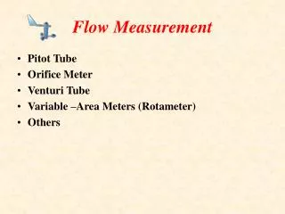
Imaging Techniques for Flow and Motion Measurement Lecture 19. Stereoscopic Particle Image Velocimetry (SPIV). Lichuan Gui University of Mississippi 2011. Test region. Test result. Example. Stereoscopic PIV. Stereo PIV system Two cameras Translation and angular configurations

E N D
Imaging Techniques for Flow and Motion Measurement Lecture 19 Stereoscopic Particle ImageVelocimetry (SPIV) LichuanGuiUniversity of Mississippi2011
Test region Test result Example Stereoscopic PIV • Stereo PIV system • Two cameras • Translation and angular configurations • Distorted particle images (angular system) • 3-D displacement reduced from two 2-D displacements • 3 velocity components in a plane G. Calcagno, F.D. Felice, M. Felli, and F. Pereira, 24th Sym. Naval Hydro. (2002)
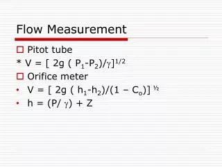
X X Laser light sheet Laser light sheet Z Z X t=t0 Z S S t=t0+t X Standard PIV view Stereoscopic PIV • SPIV data reduction Z not sensible
X1 X Laser light sheet X2 Z X Z S 1 2 camera #1 camera #2 Stereoscopic PIV • SPIV data reduction Stereo view
No stereo effect in yz-plane Stereoscopic PIV • SPIV data reduction - Particle image displacements: (X’1, Y’1) and (X’2, Y’2) - Imaging scale factor: M1 and M2
Stereoscopic PIV • Error propagation in SPIV
Stereoscopic PIV • Error propagation in SPIV
Define: Stereoscopic PIV • Error propagation in SPIV
Stereoscopic PIV • Error propagation in SPIV - Optimal view angle 45
Lens Plane Camera #1 Camera #2 Stereoscopic PIV • Translation (lateral displacement) system - Object plane || Lens plane || Image plane - Uniform magnification (Mn=di/do) - Easy to focus - Off-axis angle restricted by the lens (application limited)
Object plane Lens plane Image plane Mirror pair 1 Mirror pair 2 Image #2 Test region Image #1 Aperture stop Mirror pair 1 Mirror pair 2 Stereoscopic PIV • Translation (lateral displacement) system - Single camera configuration- View angle is limited
Stereoscopic PIV • Rotational (angular displacement) system - Scheimpflug condition - Distorted image (Mnconstant)
Distorted Image Calibrated Image Velocity map Image calibration methods Preservation of straightness of lines – for high quality camera lens Polynomial mapping Stereoscopic PIV • SPIV recording evaluation 1. Evaluation with image calibration Positive: a. Uniform spatial resolution b. Simple procedure Negative: Image interpolation error
Basic evaluation steps: 1.Determine transformation function between physical and image plane Distorted Image 2.Transfer uniform evaluation grid in physical plane to image plane Velocity map Velocity calibration 3.Evaluate the distorted SPIV recordings with the transformed evaluation grid 4.Transfer the evaluated displacement components to the physical plane Stereoscopic PIV • SPIV recording evaluation 2.Evaluation with velocity calibration Positive: No image interpolation Negative: a. Non-uniform spatial resolution b. Evaluation grid transfer required
Homework • References • Prasad AK (2000) Stereoscopic particle image velocimetry. Exp. Fluids 29, pp. 103-116 • Willert C (1997) Stereoscopic digital particle image velocimetry for application in wind tunnel flows. Meas. Sci. Technol. 8, pp. 1465-1479 • Practice with EDPIV • Compare image calibration and vector calibration with application example #9