Download
1 / 20
220 likes | 634 Views
Learn about the advantages, disadvantages, block diagram, topologies like Flyback, Push-pull, Half-bridge, and Full-bridge converters, applications, and considerations in selecting an SMPS for different devices. Discover how SMPS offers efficiency and reduced costs compared to linear power supplies.

E N D
General description of PowerSupply • Advantages/Disadvantages of SMPS • Block diagram ofSMPS • Basic topologies andpractical • requirements • Working of various SMPS topologies: 1. FlybackConverter • 2. Push-pull Converter 3. Half bridge Converter 4. Full bridgeConverter • Applications ofSMPS • Conclusion Contents:-
Any device that supplies electric power to an electricload. The different types ofpower suppliesinclude: -Battery -DC powersupply -AC powersupply -Linear regulated powersupply -Switched mode powersupply -Programmable powersupply -Uninterruptible powersupply PowerSupply:-
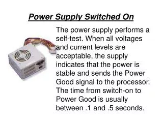
An electrical power supply that incorporates aswitching • regulator to convert electrical powerefficiently. • It transfers power from a source, to a load, while converting voltage and currentcharacteristics. • Voltage regulation is achieved by varying the ratio of on- to-offtime. Switched Mode PowerSupply:
1. Lowerweight • 2. Smallersize • 3. Higherefficiency • 4. Lower powerdissipation • 5. Wide ac input voltagerange • 6. Reducedcosts Advantages of SMPS over Linear PowerSupplies: Disadvantages ofSMPS: 1. Complexity of thecircuit
Block diagram of aSMPS 1. Input rectifierstage: It is used to convert an ac input to dc. A SMPS with dc input does not require this stage. The rectifier produces unregulated dc which is then passed through the filtercircuit.
2. Inverterstage: • – The inverter stage converts DC, whether directly from the input or from the rectifier stage described above, to AC by running it through a power oscillator, whose output transformer is very smallwithfewwindingsatafrequencyoftensorhundreds • ofkilohertz. • 3. Outputtransformer: • - If the output required is to be isolated from input, the inverted AC is used to draw the primary windings of a high frequency transformer. This converts the voltage up or down to the required output level on it’s secondarywinding. • 4. Outputrectifier: • - Ifthedcoutputisrequired,theacoutputfromthetransformer • isrectified. • 5. Regulation: • - Feedback circuit monitors the output voltage and compares it with the referencevoltage.
1. Is input-to-output dielectric isolation required for theapplication? • 2. Are multiple outputs required? • 3. Does the prospective topology place a reasonable voltage stress across the voltage semiconductors? • 4. Does the prospective topology place a reasonable current stress across the voltage semiconductors? • 5. How much of the input voltage is placed across theprimary • transformer winding orinductor? • Typical maximum output power available from eachtopology: Factors to be considered while selecting a topology for a particularapplication:-
Non isolated topologies are the simplest, with the three basic types usinga • single inductor for energystorage. Use of non-isolatedtopologies:
Working of various SMPSTopologies: 1. Flybackconverter:
Current builds up in the primarywinding • Secondary winding has the opposite polarity D1OFF • C maintains the output voltage, supplies loadcurrent Mode 1 Operation -- Q1ON
Polarity of the windingsreverses • Diode D1 conducts, charging C and providing current to the loadRL • Secondary current falls to 0 before the next cyclebegins Mode 2 Operation -- Q1 turnedOFF
Operation of the Push-PullConverter: • Q1 ON, Vs across the lower primarywinding • Q2 ON, Vs across the upper primarywinding
1. Machine toolindustries • 2. Security Systems • (Closed circuitcameras) • 3. Support supplies withPLC’s • 4. PersonalComputers • 5. Mobile Phonechargers Applications ofSMPS:-
SMPS in Indianmarkets: Cooler master550W Rs.3800 iball600W Rs.4700 Antec750W Rs.6600 Seasonic500W Rs.3600 UMAX450W Rs.570 Corsair750W Rs.10700