Download
1 / 18
220 likes | 641 Views
Digital Cartesian Feedback Linearization of Switched Mode Power Amplifiers. Alejandro Viteri, Amir Zjajo, Thijmen Hamoen, Nick van der Meijs Delft University of Technology. Motivation Linearization by means of feedback Cartesian feedback modeling Digital design Simulation results

E N D
Digital Cartesian Feedback Linearization of Switched ModePower Amplifiers Alejandro Viteri, Amir Zjajo, Thijmen Hamoen, Nick van der Meijs Delft University of Technology
Motivation Linearization by means of feedback Cartesian feedback modeling Digital design Simulation results FPGA synthesis & results Conclusions Outline
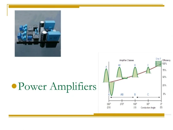
Motivation Previous version of the transceiver A linear mode power amplifier (PA) ISIS Innovative Solutions In Space New version of the transceiver A power efficient switch mode PA in the transmitter No power losses due to dissipation Improves lifetime of batteries Better use of the solar panels Non-linear
Linearization by means of feedback Feedback system with distortion • In a feedback system linearity depends on the loop gain • Distortion in the feedback is not attenuated • Better control of the system linearity is achieved Loop gain:
Cartesian feedback General model • Stability condition (PM ≥ 60o) The signal is decomposed in Cartesian components Feedback is applied to each component A delay (e-Ts ) will model the latency of the digital domain
Cartesian feedback Phase shift problem Sources of phase shift • Delays in the loop • Distortion in the PA and • Up/Down converters • Tochanges and aging
The dominant poles of this system determine the stability Oversampling allows to relax the order of the LPFs Cartesian feedback Mixed signal model Benefits • Allows integration • Reduces area usage and weight in the satellite • Low power consumption
Mixed-signal Cartesian feedback Stability analysis by root locus System root locus Compensated system root locus
Mixed-signal Cartesian feedback Phase regulation Source signals modeled as a ramp signal Transfer function of phase error
Mixed-signal Cartesian feedback Phase regulation Final value theorem:
Mixed-signal Cartesian feedback Phase regulation
Digital design Delay correction by signal rotation Magnitude signal for envelope restoration
Simulation results Amplification of 20 dB IMD -40 dBc satisfied
FPGA synthesis Spartan3 X3s50-4tq144 50K System gates 1536 equivalent logic cells
Results • Power budget 1.7 W • 33.31 mW in a FPGA • 1.96% of the total power budget • Latency of 180 ns • Slack of 220 ns for A/D and D/A † Xilinx Xpower Analyzer
Conclusions • Mixed-signal Cartesian feedback proves to be an efficient linearization method for a stable system with sufficient phase margin. • Feedback improves linearity when provided with an adequate amount of loop gain. • The results show that the use of the CORDIC algorithm proves to be a simple, low-power and robust solution for the low bandwidth input signal.