The Embedded System Design Process
1.05k likes | 1.94k Views
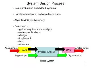
The Embedded System Design Process. Chapter 1. Designing Embedded Systems. How is designing an embedded system different from a non-embedded system? Generally speaking, there are two (sometimes three) design paths running in parallel Hardware Embedded software (often called firmware )

The Embedded System Design Process
E N D
Presentation Transcript
The Embedded System Design Process Chapter 1
Designing Embedded Systems • How is designing an embedded system different from a non-embedded system? • Generally speaking, there are two (sometimes three) design paths running in parallel • Hardware • Embedded software (often called firmware) • Host software (we won’t really address this here)
Embedded System Design Phases • Product specification • Hardware/software partitioning • Partition iteration/refinement • Independent hardware and software design • Hardware/software integration • Product testing • Maintenance and upgrade • Repeat as necessary
An Alternate View • Tool-based development cycle • Based not so much on what has to be done as on what has already been done • Available processors • Available software development tools • Available hardware development tools • Available testing support tools • Available hardware/software designs from previous projects • More on this approach when we start discussing tools
Product Specification • Two approaches • Build a device that does everything under the sun • Build a device that suites the customer’s needs • This should be a marketing function but inclusion of the design team can be beneficial (if not critical)
Product Specification • Customer Research Tour • Marketing person (1) • Leads the meeting • Asks questions, presents possible solutions • Engineering/design specialists (2 or 3) • Wait in the shadows • Provide technical support or ask/clarify technical questions • Take notes
Product Specification • Debriefing • Soon after customer meeting • Compare notes • Assess customer reactions • Translation to specification • Convert customer reactions to design requirements
Product Specification • Goals: • Get the design team (and marketing team) to share a common vision of the product • Make sure that the common vision is consistent with the market (what the customer wants) • Make sure that the tools required by the design team are available
Product Specification • This approach is the starting point for what software developers call agile methods • Extreme programming • Communication • Simplicity • Feedback • Courage • This is especially important in embedded systems design because of the integrated hardware/software complexities
Product Specification • Digital cellphone camera example • This was not done! • Engineers were not consulted • Marketing data was poorly gathered • Marketing personnel reacted to customer “wants” with “sure, we can do that” • Unfortunately, every customer wanted something different from the rest • It was “give them everything including the kitchen sink” • Recipe for disaster – and that’s how it turned out
Hardware/Software Partitioning • The partitioning decision • Which part of the solution will reside in hardware and which part in software? • Specify the desired algorithm as a sequence of processing stages • Map processing stages to either hardware or software
Hardware/Software Partitioning • Decision criteria • System performance requirements • Future upgrades • Development cost • End product cost • Time to market (market competition) • Intellectual property protection • Standard vs. non-standard components • Market leader or market follower • These criteria can (and do) conflict with one another
Hardware/Software Partitioning • Designers may choose an evolutionary path • Start with items in software for initial product release • Move to hardware for subsequent releases • Reduces • Initial time to market • Development cost • Opportunity to reduce product cost on subsequent releases • Ultimately, it comes down to experience
User Interface Sensor Host Support Control Color Image Processing Image Compression Image Storage Hardware/Software Partitioning • Digital cellphone camera • There are many HW/SW partitioning possibilities
Partition Iteration/Refinement • Last chance before hardware and software paths diverge • Dependence on tools to validate (or invalidate) the partitioning decision • Hardware designers use simulation tools to model performance • Software designers use evaluation boards (like the Stamp boards) to develop and benchmark code
Partition Iteration/Refinement • Nowadays, the time when the hardware and software paths diverge is being pushed further out • The toolsets are sophisticated enough to provide confidence in the decision while not holding off development
User Interface Sensor Host Support Control Color Image Processing Analog hardware Software → Digital hardware → Analog hardware Image Compression Digital hardware Image Storage Software Partition Iteration/Refinement • Digital cellphone camera
Independent Hardware and Software Design • These are specific to • The task at hand • The field (hardware or software) • Various design practices exists • Some will be discussed later but, realistically, these are topics of individual classes, if not entire degrees and specialties • Software engineering • Electrical engineering • Analog circuit design • Digital circuit design • Systems engineering • Mechanical engineering • etc.
Hardware/Software Integration • Exercise in debugging and discovery… • and frustration • Hardware not built as originally designed • Software not written as originally designed • Errors in the hardware that can’t be fixed within allotted time/budget • Additional software to compensate for hardware shortcomings
Hardware/Software Integration • System works but… • Is too slow • Doesn’t meet quality needs • Late to market • No longer meets customer needs • …
Hardware/Software Integration • System doesn’t work so… • Focused Ion Beam (FIB) chips • Add wires to board • Cut traces in board • Add “dead-bugs” to board • Repartition hardware functions into software • Remove software functionality • Rewrite software • …
Hardware/Software Integration • These things occur for various reasons • Communication problems • Lack of communication • Lack of a common language • Complex, non-deterministic behaviors • The tools go only so far • Design optimism • Original design goals were just too aggressive
Hardware/Software Integration • Digital cellphone camera • Due to the complexity of the analog circuitry there was a fair amount of repartitioning • i.e. fix it in software and we’ll re-spin the hardware next time • Produced a suitable solution but was considerably slower than originally specified • It reverted back to a marketing problem • i.e. this is what we have, figure out how to sell it
Hardware/Software Integration • Digital cellphone camera • Subsequent product revisions moved software functionality into digital hardware • Increased processing speed • Reduction in product cost • Of course the cost of the “improvements” is loss of flexibility • Again, this ultimately becomes a marketing problem
Product Testing • Requirements are generally more stringent than for a software only system • We can no longer live with • “just reboot when it hangs up” • “it’s only a small memory leak” • “oh well, it’s fast enough” • Embedded systems often run for long periods of time between resets • Testing must ensure system integrity over these long periods • Testing must expose every nuance of the system
Product Testing • Embedded systems are often placed in environments where the PC dare not go • Extreme temperatures • Extreme impacts • Extreme vibrations • Extreme dirt and filth • etc… • The product must be tested under all of these conditions
Product Testing • A well thought out test plan developed at the beginning of the product life cycle (the requirements phase) can alleviate [some] testing pains • What to test (specify the features to be tested) • How to test (specify the tests) • Test oracle (specify the expected answers) • Test group (who will perform the tests and who will evaluate the results) • Test response (what to do with the results)
Product Testing • Digital cellphone camera • Testing poses a real problem • Some things were easy in that they either worked or the didn’t • Some things were difficult in that they are very subjective • “that image is too blue” … “no, it’s too red” • “it’s not vibrant” • “it’s too hazy” • “it’s too bright” … “no, it’s too dark” • Basically, people started making up terms and measures for which there is no way to test • I believe it was due to poor marketing, relating back to the lack of that initial customer research tour (but then I’m an engineer)
Product Testing • Digital cellphone camera • And that was just the image quality… • Environmental testing required exotic test setups • Special heat chambers • The “drop test” • “burn in” testing (testing over time) • Production testing • Can only spend seconds per part or you’re losing money
Maintenance and Upgrade • Time to market is perhaps the most critical design goal today • To meet the time to market goal many embedded systems products get to market with… • Reduced feature sets • Known bugs • Suboptimal hardware/software partitioning • Maintenance and upgrade engineers address these shortcomings
Maintenance and Upgrade • Often it is a different team of engineers with no overlap with the original design team • Can’t afford not to put your best designers on your newest products • Often there are constraints of not making any major changes • Any new hardware must be “plug-compatible” • Any new software must fit into the current architecture • These constraints often lead to a “family of products”
Maintenance and Upgrade • Bottom line is it isn’t always fun and is rarely appreciated • Who wants to here about fixing old stuff when someone is talking about building new stuff
Maintenance and Upgrade • Digital cellphone camera • Move software processing into hardware while maintaining chip compatibility • Add more pixels to the sensor while maintaining software compatibility • Fix design errors • Generally it’s a “fix it in software” mentality because the market moves so fast and new hardware designs take time
Tonight’s Lab Testing
Testing Pins • Your Basic Stamp board has • 32 connectors for I/O pins (2 connectors/pin) • 6 Vdd connectors • 7 Vss connectors • It is important to know that all connectors are working prior to embarking on a large scale project
Testing Pins • To Do • Download the test report • Download the test circuit designs • Download the test software • Perform tests • Yes, this is tedious and seems unnecessary…welcome to the world of embedded systems design
Homework/Project • Homework #2 – see handout • Project #2 – see following charts
Stoplight Timeline North/South East/West repeat forever tbutton+41 tbutton+52 tn tbutton+10 tbutton+21 tbutton tbutton+51 tbutton+20 • Note: While this diagram depicts a fixed time interval scheme. Your code should provide variables so that the scheme can be easily changed.
In words… • Initial condition: Light 1 is red, light 2 is green • Press button (to signify car waiting) • Pause – long • Light 2 turns yellow • Pause – short • Light 2 turns red • Pause – short • Light 1 turns green • Press button (to signify car waiting) • Pause – long • Light 1 turns yellow • Pause – short • Light 1 turns red • Pause – short • Light 2 turns green • Goto step 2
Deliverables • A state-machine diagram depicting the operation of the system • Source code • A schematic diagram of the circuit • A working demonstration on the Basic Stamp development board (in class)