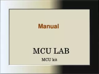
MCU LAB
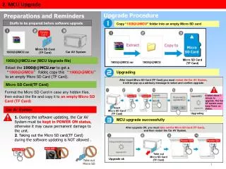
Manual. MCU LAB. MCU kit . Contents. Introduction…………1 Main PCB…………2-3 Outputs…………4-5 Inputs…………6-8 Software…………9-12 Software Samples…………13-19. Introduction.

MCU LAB
E N D
Presentation Transcript
Manual MCU LAB MCU kit
Contents Introduction…………1 Main PCB…………2-3 Outputs…………4-5 Inputs…………6-8 Software…………9-12 Software Samples…………13-19
Introduction MCU LAB is a complete system of hardware and software, that includes very high language(VHL) in which any student within few hours and with maximum learning and minimum teaching , can easily program the MCU and apply his own ideas. In addition, its much easier to work with it than either using the traditional (C) or assembly language, giving them the base to an unlimited path of invention and innovation, since the MCU is the core of all technological advances. In this system there is no need for any programming devices(programmers), making it very affordable and much less complicated. Also, a privileged advantage has been added to the system, which is the direct download method through (USB). And the student can download one hundred thousands times, whereby the new code that is being downloaded will over write the previous one so it would be easier for the student to deal with it. In this case students or anyone who is using the system, would get the privilege to be a part of a generation that will create a real revolution. The main aim of this lab is, to open a new path for students to use there super mass of ideas and creations, and give them the only tool they need to keep updated with all the technological developments, and even to add and innovate solutions to problems they would realize. 1
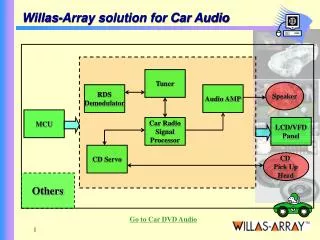
MainPCB(MCU Kit) Sound output On-Off Switch General input Fan/BD LED-0 output Battery input Fan/BD LED-1 output USB Cable input Onboard LED Generaloutput 2
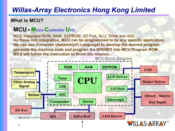
Main MCU Start Program Switch EEPROM(Memory- Chip) 3
Outputs: 1-Sound output, is dedicated to display sound such as Beep, Music, Tone actions. 2-Moto0 and Moto1, each contains two outputs, Forward and Backward. 3-Onboard LED, it is a Light Emitting Diode. 4-Genral output can be connected to RF module, Infra Red Transmitter module(IRT), or GSM module. RF: Radio Frequency module, in the off case it well send a signal to trigger a remote device connected with an AC current(220V)through an RF receiver with relay will be on. In the on case, the relay will be off. In both cases it can control remotely any device connected to the AC Main. The controlling depends on coding and sensor in use. Motor forward/Green on: Is used for Motor output, and for this output we use, bi directional LED, or a Motor. For the bi directional LED, it lights green. For the Motor, it turns forward. Motor backward/Red on: Is used for Motor output, and for this output we use, bi directional LED, a Motor, or a Fan. For the Bi directional LED, it lights red. For the Motor, it turns backward. For the Fan, it turns backward. Notice: The Fan only turns backwards, so in forward action it will not turn. There are tow outputs on the main PCB, one is Moto- 0,the other is Moto 1. Both indicates the same action giving Varity of orders. GSM Module: The Module would be connected to general output, when the output is triggered Off, the Module well send a pre-recorded message as a SMS or Code to any desired telephone or mobile. Digital Recorder:This module will display a pre-recorded voice message according to the asked needs when the output is triggered Off. LED Screen Module: This display a pre-designed message on the screen when the output is triggered Off. 4
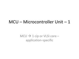
Some outputs Fan Bi-directional LED LED Screen GSM Module RF Transmitter Module 5
Inputs: 1-Contact sensor(Jumper), when its inserted it passes the current, so the input is off. When its not inserted, the current cannot pass, so the input is on. Ex, car’s switch, door contact sensor, etc. 2-Light sensor(CdS) Cadmium Sulfite, also is called(LDR). This sensor will be in Off state when there is light, when there is less light it will be On. Ex, Automatic Lighting, Street Lighting , etc. 3-Tempreture sensor(NTC)-Negative Temperature Coefficient,(PTC)-Positive Temperature Coefficient. NTC: If there is high temperature its Off, if there is low temperature its On. PTC: If there is high temperature its On, if there is low temperature its Off. Ex, Air Conditioners, Refrigerators, Heaters, etc. 4-Level sensor, if its vertical Off, horizontal On. Ex ,Electrical Heater, etc. 5-Infra Red Receiver(IRR), when there is Infra Red its Off. Ex, Automatic Doors, Automatic Tabs. 6-Intrusion sensor, it can detect any movement in the range of 7meters. Ex, Security Systems, Economy Lighting, etc. 7-Piezo sensor, its used to detect sound and vibration. Ex, Earth Quake Alarms, Deaf People Devices, etc. 8-Magnetic Switch sensor, if there is magnet in the range, its Off. 9-Humidity sensor: for high humidity its On. Ex, Humidity Regulators, etc. 6
10-Gas sensor, if there is gas its Off. Ex , Gas leakage Detectors, etc. 11-CO2 sensor., when there is high CO2 its Off. 12-O2 sensor, when there is high O2 its Off. 13-Ultra Sonic sensor, when the Ultra Sound is interrupted it On. Ex, Proximity sensor, etc. 14-Smoke sensor, if there is more smoke it Off. Ex, Smoke Detectors, etc. 15-X-Ray sensor, it detects object in a range even In a briar presence. Ex, Intrusive Alarm, etc. 16-Ultra Violate sensor, if it detects ultra violate the sensor is Off. Ex, Ultra Violate Alarm, UV Glasses Testing, UV Cream Testing, etc. 17-Presure sensor, detects the difference in pressure, when its under high pressure its Off. 7
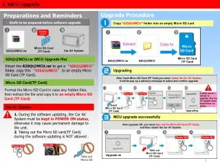
Some inputs Contact sensor Temperature sensor Light sensor Humidity sensor Microwave sensor Ultrasonic sensor RF Receiver module Gas sensor Intrusion sensor Smoke sensor 8
Software Icons Program Icon New sub, To start a new sub Delete sub, To delete named Subs New, To start a new project Download, To download selected projects to MCU Open and Export, To open a pre-saved project Beep, To give sound output the order Beep(voice) Export, Save and Save as, To Save aimed project Stop, To stop action from continuing order Draw Line, To draw a line between the loop start and loop end Onboard LED, To give Onboard LED light On Off action Delete Line, To delete selected lines between loop start and loop end 9
Music, To give sound output a pre-recorded Melody order(voice) Motor forward, Gives order to output Motor 0-1 to move forward Motor backward, Gives order to output Motor 0-1 to move backward Delay 1 second, To delay action for 1 sec only Motor stop, Gives order to output Motor 0-1 to stop action Delay, To delay action for an open time Tone, To compose melodies for sound output Set output on, Gives order to General output to turn on Sensor(IF), Triggers the desired output to turn On or Off, to the applied Sensor Set output on, Gives order to General output to turn off 10
To call sub Sub: Are used in the need for common use of tasks order, and to reduce number of tasks on main Logic Graph(LG). For making a sub, press on new sub icon and name the selected sub. Then to call the aimed sub, drag an drop sub icon from the Instruction Selector , and name the aimed sub under sub name to be called. To delete sub, press on delete sub icon then choose the aimed sub from the list. To delete sub To start a new sub To name called sub 11
Loops: Loop icons are used to repeat a task until specified conditions are fulfilled, or to perform the loop a set number of times. Note that you will need to add calculation icons that modify the variables used for the condition in order for the condition to be fulfilled. And there are two types of loops limited and unlimited loop, each for its suitable appliance. Limited loops are needed to set the number of times the action to be repeated, and the number can be set between 1-255 times. Unlimited loop is when the task is needed to work for an infinite period. To apply it :press on the loop icon, choose your proposed choice and apply the loop start icon on flowchart before the desirable action to be repeated. After ending the task apply the same loop icon notice to choose the loop end icon. To have a closed task order, press on the drew line icon and then press on the applied loop icon and dragged form one to the other. For the unlimited loop you only need to apply the instructions above. For the limited loop you need to set the number of times needed for each loop, note to match the selected loop icon start number with loop end. To erase the line between loops you can press delete line and then double click on the selected line. Sometimes you need to apply tow actions with same unlimited loop, as in the IF case. In that case you apply one unlimited loop start and on one end unlimited loop end, and the other end apply the icon jump, which indicates the same action as unlimited loop end dose. And then you draw line for each end. 12
Press on the aimed icon, drag while pressing and drop when its on the right place of the LG. 13
To draw a line press here This sample is to make the onboard LED blinking eight times(on-off). 1-Drag and drop the Limited loop 1 start icon as to repeat the action 8 times. 2-Drag and drop the Onboard LED icon and set it on. 3-Drag and drop the Delay icon and set the unit and number of times, 0.01 sec-one time. 4-Drag and drop the Onboard LED and set it off. 5-Drag and drop the delay icon and set the unit and number of times, 1 sec-three times. 6-Drag and drop the Loop 1 end icon. 7-Press on draw line icon, and drag the line form loop 1 start, to loop 1 end icon. The next step is to press on download icon, and download the code. To Select aimed unit and number of times, click here 14
To delete line press here To delete Click on selected line double click 15
This sample is to make a Beep Alarm for 9 times. 1-Drag and drop Loop 1 start icon and set it for 9 times. 2-Drag and drop Beep icon . 3-Drag and drop Delay icon and set unit and number of times, 0.1 sec-three times. 4-Drag and drop Loop 1 end icon . 5-Press on draw line icon. 6-Drag line from Loop 1 start, to Loop 1 end icon. 16
This sample is to make an Alarm for an unlimited number of times, using(unlimit loop). 1-Drag and drop unlimit loop start icon. 2-Drag and drop Beep icon. 3-Drag and drop delay icon and set unit and number of times, 0.1 sec-three times. 4-Drag and drop Unlimit loop icon. 5-Press on Draw line icon. 6-Drag line from Unlimit loop start, to Unlimit loop end icon. Notice: To delete dropped icons, click on Mouse’s right click and press on(Del) 17
This sample is to make a Heat alarm using(temperature sensor). 1-Drag and drop Unlimit loop start icon. 2-Drag and drop If icon. Notice that creates tow cases, off and on. In the sensor Off case: 1-Drag and drop Moto Backward-Red LED on icon. 2-Darg and drop Delay icon and set it 0.3 sec. 3-Drag and drop Moto stop icon. 4-Drag and drop delay icon and set it 1 sec 5-Drag and drop Unlimit loop icon, and draw line. In the sensor On case: 1-Darg and drop Moto Forward icon-Green LED on icon. 2-Drag and drop Delay icon and set it 0.3 sec. 3-Drag and drop Moto stop Icon. 4-Darg and drop delay icon and set it 1 sec. 5-Drag and drop Jump icon, and draw line. Notice, in the IF case we use Jump and Unlimit loop end icons. In this case, any other sensor can be used instead of the temperature sensor Green LED on Red LED on 18 18
This sample is to compose a melody: To compose a melody, use the Tone icon and set length and tone type. 1-Select Unlimited loop start icon. 2-Select Tone icon and set as following: 1-1/4 1-1/4 5-1/4 5-1/4 6-1/4 6-1/4 5-3/8. 3-Select Delay icon and set it 0.01 sec. 4-Select Tone icon and set as following: 4-1/4 4-1/4 3-1/3 3-1/4 2-1/4 2-1/4 1-3/8 . 5-Select Unlimited loop end icon. 6-Draw a line from Unlimited loop start to Unlimited loop end. 19