Download
1 / 11
110 likes | 177 Views
SPP FIELDS Updated block diagrams Fault Tolerant Design. Fault Tolerance Requirement.

E N D
SPP FIELDS Updated block diagrams Fault Tolerant Design
Fault Tolerance Requirement • “Solar Probe Plus will achieve mission success at the end of prime mission by returning no less than 64 Gb of science data composed of at least 7 out of 9 of the required measurements (4.1.2.3 -4.1.2.11) collected during 150 hours below 20 Rs, including no less than 5 hours below 10 Rs. “ • Since FIELDS measurements represent 4 of the 9, any single point failure in FIELDS is a mission critical failure. FIELDS threshold mission science measurements:
FIELDS fault tolerant design “Sys-6”, TDS serves double duty, serves as DCB for Side 2
Capabilities retained • Side 1 failure, Side 2 carries on FIELDS operations • Inboard MAG • Produces magnetic field vectors, 3 axes, up to 293 Sa/s • TDS • Can deliver DC electric field vectors, DC to 1MSa/s, one axis (V3,V4) • Can deliver electric field spectra, up to 1MHz BW, one axis (V3,V4) • Requires some re-programming of TDS function • Total loss: • SCM • QTN and Radio Emissions • Side 2 failure, Side 1 carries on FIELDS operations • Outboard MAG • Produces magnetic field vectors, 3 axes, up to 293 Sa/s • DFB • Produces electric field vectors and spectra, DC to 150 kSa/s, two axes (V1,V2) and V5 • Produces SCM vectors and spectra, DC to 150kSa/s, 3 axes • RFS/DCB • Produces QTN spectra, 10kHz to 2.5MHz BW • Produces Radio Emission spectra, 1MHz to ~19MHz BW • Total loss: • TDS
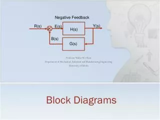
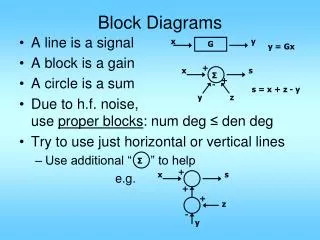
Block Diagram Jun 4, 2013
MEP Stack Up • Side 1 • LNPS1 • MAGo (Outboard) • DCB/RFS • AEB1 • DFB • Side 2 • LNPS2 • MAGi (Inboard) • TDS • AEB2 • Each slice is bolted to S/C Panel
Level 3 Requirement - Clarification • Current L3 max field intensity: 5V/m at 20kHz • Applied to V5 measurements implies signals that are 10s Volts amplitude • Not met with current design of V5 preamp • Should we clarify this requirement as N/A for Eparallel? Current Level 3 Requirement for EFI…
SCM noise floor question • A request from DFB to SCM team: • “recommended that the sensitivity of the complete SCM including Preamp be verified before moving forward on the DFB design.” • Meeting SCM noise floor L3 requirement would more power • L3 requirement is 10X the published SCM noise floor • Noise floor analysis of SCM preamp, based on • LT1352 preamp LF output stage, noise referred to its input: 14nV/sqrt(Hz) Indicated gain implies ~450nV/sqrt(Hz) at the output • SCM-LF noise floor (at 3kHz): 1E-5 nT/sqrt(Hz) converts to 26nV/sqrt(Hz) • Assuming conversion factor of 2.6mV/nT