Download
1 / 44
440 likes | 491 Views
Explore fault-tolerant routing techniques that balance performance and fault tolerance in interconnection networks, avoiding deadlocks and livelocks. Learn about redundancy, fault regions, and fault rings in achieving dependable routing.

E N D
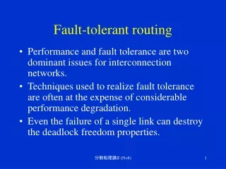
Fault-tolerant routing • Performance and fault tolerance are two dominant issues for interconnection networks. • Techniques used to realize fault tolerance are often at the expense of considerable performance degradation. • Even the failure of a single link can destroy the deadlock freedom properties. 分散処理論2 (No8)
misrouting • Misrouting can avoid deadlocks caused by faulty components. • It must be controlled so that livelock is avoided and newly introduced dependencies do not produce deadlock. • Fault-recovery mechanisms must recover messages indefinitely blocked on faulty components. 分散処理論2 (No8)
Channel and network redundancy • A network is said to be connected with respect to a rouging algorithm if the routing function can route a message between any pair of nonfaulty routing nodes. • A channel is said to be redundant iff, after removing it, the resulting routing function is still connected and deadlock-free. • A routing function is said to be ffault-torelant if for any f failed components in the network, the routing function is still connected and deadlock-free. 分散処理論2 (No8)
Redundancy level • A routing function has a redundancy level equal to r iff after removing any set if r channels, the routing function remains connected and deadlock-free, and there exists a set of r+1 channels such that, after removing them, the routing function is no longer connected or it is not deadlock-free. 分散処理論2 (No8)
Fault regions Convex fault region 0,3 1,3 2,3 3,3 Concave fault region 0,2 1,2 2,2 3,2 0,1 1,1 2,1 3,1 0,0 1,0 2,0 3,0 分散処理論2 (No8)
Fault model • The patterns of component failures and expectations about the behavior of processors and routers in the presence of these failures determines the approaches to achieve deadlock and livelock freedom. • On a node (PE or router) failure, all physical channels incident on the failed node are also marked faulty at adjacent routers. • On a link failure, all VCs on that particular physical link are marked faulty. 分散処理論2 (No8)
Fault-tolerant model attributes 分散処理論2 (No8)
An example of misrouting 1111 0111 1110 0110 x 1010 1011 0010 0011 1100 0100 1101 x Faulty links 0000 1001 1000 0001 分散処理論2 (No8)
Chaotic routing • Incorporates randomization to produce a nonminimal fault-tolerant routing algorithm using VCT switching. Input Deroute output Input Deroute output 分散処理論2 (No8)
Unsafe/faulty nodes Faulty nodes 0,3 1,3 2,3 3,3 0,2 1,2 2,2 3,2 Unsafe nodes 0,1 1,1 2,1 3,1 0,0 1,0 2,0 3,0 分散処理論2 (No8)
Graph search • Routing algorithms based on graph search techniques provide the maximum flexibility. • First a message is transmitted along a link on the shortest path to the destination. • If all such paths are blocked by faulty components, the message must be misrouted to a neighboring node. • We wish to avoid visiting any node more than once except for a backtrack. 分散処理論2 (No8)
An example of depth-first search (SAF) 1111 0111 1110 0110 1011 0011 1010 0010 1100 0100 0101 1101 x x 0000 x 1001 1000 0001 x Faulty links 分散処理論2 (No8)
Deadlock and livelock freedom • For SAF networks, message buffers within each router are partitioned into B classes. • These classes are placed in a strict order. • Within a known maximum distance and a corresponding number of buffers at each node, buffers are occupied in strictly increasing order. 分散処理論2 (No8)
Structured buffer pool Maximum path length n, and (n+1) buffer classes 分散処理論2 (No8)
Fault-tolerant routing in wormhole switched networks • Planar-adaptive routing for 2-D mesh networks adds one additional VC in the vertical direction to partition the network into two virtual networks. • The only case where a message will be misrouted is when the destination node is in the same column or row, and the message is blocked by a fault region. 分散処理論2 (No8)
Fault-tolerant Planar-adaptive routing rectangularfault region Increasing network Decreasing network 分散処理論2 (No8)
Fault rings (1/2) • Some fault-tolerant routing algorithms can not treat a concave fault region. • Ensuring that fault regions remain convex will require marking fault-free nodes as fault. • Fault rings were proposed to support flexible routing around fault regions. • A fault ring is the sequence of links or nodes that are adjacent to, and surround a fault region. 分散処理論2 (No8)
Fault rings (2/2) • Rectangular fault regions will produce rectangular fault rings. • If a fault region includes boundary nodes, the fault ring reduces to a fault chain. Fault ring Overlapping Fault ring Fault region Fault chain 分散処理論2 (No8)
Routing around a fault region (1/2) • For dimension-ordered routing in a 2-D mesh with nonoverlapping fault rings and no fault chains, only two VCs (C0 and C1) are required for routing around rectangular fault regions (F). C1 C1 C0 C0 F F F F 分散処理論2 (No8)
Routing around a fault region (2/2) • For dimension-ordered routing in a 2-D mesh with overlapping fault rings and fault chains, four VCs (C0, C1, C2 and C3) are required for routing around rectangular fault regions (F). C2 C3 C0 C1 F F F F 分散処理論2 (No8)
An example of routing around overlapping rings A is an East-West message. B is West-East message until it reaches the destination column where the type is changed to North-South message. Fault ring Fault region A B 分散処理論2 (No8)
Origin-based routing (1/2) • Origin-based routing enables fault-tolerant routing without the addition of VCs. • Each message progress through two phases. • Firstly, a message is adaptively routed to a special node. • Secondly, on reaching the special node, the message is adaptively routed to the destination node. • This special node is designated as origin. • When the origin is placed at the corner of a mesh, congestion around it is minimized. • Placing the origin at the center will improve adaptivity, but increases hot spot contention. 分散処理論2 (No8)
Origin-based routing (2/2) destination Fault region source origin 分散処理論2 (No8)
Software-based fault-tolerant routing (1/2) • In environments where the fault rates are relatively low, the use of expensive, custom, fault tolerant routers cannot be justified. • In such environments, software-based rerouting can be a cost-effective and viable alternative. • When a message encounters a faulty link, the message-passing software computes an intermediate node address and reinjects the message into the network. 分散処理論2 (No8)
Software-based fault-tolerant routing (2/2) Fault region Intermediate node source destination 分散処理論2 (No8)
Fault-tolerant routing in PCS • Potential paths form the source to destination are searched by routing header flit through the network along a path following a depth-first search of the network. • When the header is blocked by a fault, and non of the output channels along a path to the destination are available, it may be routed along nonminimal paths. • When all candidate output channels are busy, the header backtracks over the last acquired link. 分散処理論2 (No8)
An example of backtracking 0,3 1,3 2,3 3,3 0,2 1,2 2,2 3,2 x misroute 0,1 1,1 2,1 3,1 x x 0,0 1,0 2,0 3,0 backtrack 分散処理論2 (No8)
misrouting backtracking (1/2) • One approach to use PCS for fault-tolerant routing. • A set of misrouting algorithms with the routing restriction that less than or equal to m unprofitable links may be allowed, is referred as MB-m. • Livelock freedom is guaranteed by limiting the number of misroutes. • These algorithms suit for the systems that experience large periods of unattended operation or high fault rates. 分散処理論2 (No8)
misrouting backtracking (2/2) • The MB-m algorithms are conservative in the sense that data flits are not injected into the network unless the path has been setup. • However, when the message sizes are small and fault rates relatively low, the overhead of a prior path setup can be substantial. • Multiphase routing algorithms use both the PCS style flow control in a faulty phase and wormhole switching in a fault-free phase. 分散処理論2 (No8)
Two-phase routing (1/2) • Message routing proceeds in one of two phases: an optimistic phase for routing in fault-free network segments and a conservative phase for routing in faulty segments. • The optimistic phase uses a fully adaptive, minimal, deadlock-free routing. • The conservative phase uses a form of MB-m. 分散処理論2 (No8)
Two-phase routing (2/2) Failed node source Optimistic phase destination MB-3 mode 分散処理論2 (No8)
Dynamic fault recovery • To support dynamic faults, flit-level or message-level recovery is required. • In the flit-level recovery, a message interrupted by a dynamic fault, is partitioned into two messages. • Data flits on the header side of the fault continue toward the destination. • Data flits on the other side must construct a new header and reroute this new message along an alternative path. 分散処理論2 (No8)
Flit-level recovery Faulty link New header 分散処理論2 (No8)
Choosing a fault-tolerant routing Hardware-based MTTR Software-based MTBF 分散処理論2 (No8)
Message-level recovery • Find and discard the interrupted message and retransmit the message from the source. • A link controller at the source end of the faulty link introduces a release flit. • The release flit is routed back to the source router to retransmit the message. • A link controller at the destination end of the faulty link introduces a forward flit to cancel the message. 分散処理論2 (No8)
Link level error control • Link logic modules at the two ends of the link work together to detect, contain, and recover from bit errors on the link. • Gaussian noise on a channel • Alpha-particle strikes on memory or logic • Link logic acts to mask link errors and shut the link down when errors cannot be masked. • In the event of a hard error, the link logic either reconfigure the link around the error. 分散処理論2 (No8)
Link monitoring • Error detection at the link level is performed by encoding redundant information on the link, using an error control code (ECC). • Simple parity is used to detect any single bit error. • Most links use a cyclic-redundancy check (CRC) of sufficient length that the probability of a multibit error going undetected becomes vanishingly small. • Many routers perform checks on every flit to avoid error propagation. 分散処理論2 (No8)
Link –level retransmission Retransmit control Error check Input unit Tx flit buffer 分散処理論2 (No8)
Timing diagram Tx channel F1 F2 F3 F4 F5 F6 F2 F3 F4 F5 F6 Rx channel F1 Er F3 F4 F5 F6 F2 F3 F4 F5 F6 Rx ack A1 Er - - - - A2 A3 A4 A5 A6 Tx ack A1 Er - - - - A2 A3 A4 A5 A6 F2 is received in error. The receiver signals the transmitter to retransmit. 分散処理論2 (No8)
Channel reconfiguration Tx Rx Tx Rx D3 D2 D1 D0 D3 D2 D1 D0 D3 D2 D1 D0 D3 D2 D1 D0 An 4-bit channel with 1 spare bit. Bit 2 of the channel fails and the channel is reconfigured by shifting bits 2 through 3. 分散処理論2 (No8)
Hard router error (1/2) • Router errors are most easily detected by duplicating the router logic and comparing an exclusive-OR of representative signals on a cycle-by-cycle basis. • One copy of the router logic is the master and generates all primary outputs. • The second, shadow copy of the logic receives the same inputs as the master copy, but its outputs are unused except to compare against the master. • Router errors are also detected via consistency checks, e.g. there is at least one tail flit between two head flits. 分散処理論2 (No8)
Hard router error (2/2) • Once a router error is detected, the error must be contained and recovered. • The simplest method of containment is to stop the router or the portion of the router. • If the error is transient, the router may be able to restarted after resetting all state. Otherwise, replacement is necessary (hot swapping). • When the failed component is recovered, it must synchronize its state with that of adjacent modules. 分散処理論2 (No8)
Network-level error control • At network level, we model link and router failures as fail-stop links and routers must route packets around these failed components. • The fail-stop (out-of-service) links are made unavailale and all packets are routed using one of the remaining available links. • It is realized using (non-minimal) adaptive routing. • Network level error control can also be realized with table-based oblivious routing, although the routing tables should be recomputed. 分散処理論2 (No8)
Report theme • Select one or more topics from what you have learned in this lecture, or decide a distributed and network related theme that you are interested in, then discuss about it (them) into 3-5 pages in your report. • Add one more page and refer your impression, requests or complaints to this lecture. • Mail your report to yosinaga@is.uec.ac.jp until 2/18. 分散処理論2 (No8)