Download
1 / 48
480 likes | 782 Views
Camera Overview Nadine Kurita Project Manager LSST DOE CD-1 Review November 1 - 3, 2011. Outline. Camera Project Overview Camera Design Overview Design Reviews & Project Risks Cost & Schedule Summary. Project Overview.

E N D
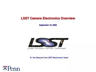
Camera OverviewNadine KuritaProject Manager LSST DOE CD-1 ReviewNovember 1 - 3, 2011
Outline Camera Project Overview Camera Design Overview Design Reviews & Project Risks Cost & Schedule Summary
A Broad-based Collaboration of Institutions Has Been Assembled to Deliver the Camera • SLAC National Accelerator Laboratory: • Overall project management, camera body and mechanisms, cryostat subsystems, data acquisition and camera controls, integration and test • Brookhaven National Laboratory: • Science sensors, electronics and raft assemblies • Lawrence Livermore National Laboratory: • Optics, corner raft assemblies, wavefront sensing • Fermi National Laboratory: • DAQ Analysis tools • Institut National de Physique Nucleaire and de Physique des Particules (IN2P3-Collection of multiple labs): • Front-end electronics, sensor testing, filters, filter carousel, camera calibration, slow controls • University-based instrumentation groups: • Harvard, U. of Pennsylvania, Purdue, Ohio State, U. of Illinois, UC Santa Cruz, U. of Arizona, U. of Tennessee, UC Davis
Contributors – Camera Team SLAC A. Roodman O. Saxton R. Schindler J. Singal S. Tether G. Thayer M. Turri BNL J. Frank J. Fried J. Haupt I. Kotov P. O’Connor S. Plate V. Radeka J. Stewart P. Takacs Purdue E. Alagoz K. Arndt A. Biccum B. Erny I. Shipsey B. Xin K. Ziegler SLAC D. Arnett T. Azemoon G. Bowden C. Brackett D. Burke R. Claus S. Digel M. Foss K. Gilmore G. Guiffre P. Hascall J. Hodgson M. Huffer W. Innes T. Johnson S. Kahn J. Ku N. Kurita J. Langton H. Leung D. Marsh S. Marshall M. Nordby F. O’Neil E. Ortiz J. Panetta A. Rasmussen K. Reil • IN2P3 • B. Amade • P. Antilogous • E. Aubourg • A. Barrau • Y. Cargagno • J. Colley • G. Daubard • C. DeLaTaille • C. Evrard • R. Flaminio • J. Giraud • L. Guglielmi • C. Juramy • P. Karst • D. Labat • H. Lebbolo • D. Martin • M. Migliore • N. Morgado • Y. Orain • E. Perbet • F. Riviere • S. Russo • D. Terront • V. Tocut • C. Vescovi • F. Vezzu • D. Vincent • F. Virieux • LLNL • B. Bauman • D. Carter • S. Olivier • V. Riot • FNAL • E. Gottschalk • C. Green • J. Kowalkowski • Harvard University • S. Amato • N. Felt • P. Doherty • J. Geary • J. Oliver • U Penn • N. Dressnandt • G. Mayers • M. Newcomber • M. Reilly • O. Rifki • R. Van Berg • U of Arizona • E. Cheu • K. Johns • D. Tompkins • Ohio State • K. Honscheid • UC Santa Cruz • T. Schalk • U Tenn/ORNL • B. Blalock • C. Britton • N. Ericson • P. Stankus • University of Illinois • J. Hart • J. Thaler • Inst. Physics Czech • P Kubanek • M. Prouza • UC Davis • T. Tyson • UC Berkley • G. Jernigan • Color Key • Institution • Manager • Contributor
Key Staff Identified and Management Structure is Well Understood • Key managers have been appointed in these areas: • Project Office, System Engineering, Project Administration, Performance & Safety Assurance Managers • Recent addition to lead Quality Assurance • Large sub-systems are led by: • Sub-System Manager (physicist) • Engineering Manager/Sub-system Architect
Product Oriented WBS is Well Defined and Used to Organize All Aspects of the Sub-systems Delivery • LCA-125, WBS Dictionary
Responsibility Assignment Matrix Defines the Accountability of WBS Deliverables • More detailed RACI (Responsibility, Accountability, Consulted, Informed) is being developed
Key Technical Challenges that Drive the Camera Design • 3.2 Gigapixel camera, large focal plane (63.4-cm diameter) with small (10 micron) pixels • 189 sensors, 4 side buttable with 250 micron interchip gaps • Deep, fully depleted CCDs with novel AR coating allow for broad spectral coverage • Fast readout (3.2 Gigapixels in 2 seconds) led to sensors with 16 segments • Low noise coupled with the large number of signal lines • Analog and digitizing electronics in the cryostat • Increased capacity needed for focal plane cooling system • Tight constraints on envelope, mass, and dissipation of heat to ambient • Tight alignment and flatness tolerances (13.5 micron p-to-v) on the sensor array • Large curved filters with broad spectral coverage and tight uniformity • As this is the only instrument for the observatory, it needs to provide 10 years of continuous operation (reliability and maintainability)
Designs Meet the Tight Constraints and All Subsystem Interfaces to Camera are Defined M2 Mirror • Key interfaces: • Weight, • Size, • Heat, • Utilities, • Handling, • Controls. Camera M1M3 primary mirror Cross section through telescope and camera
System parsed into constituent elements Understand their functionality and how they fit and work together Camera Layout Focal plane Utility Trunk—houses support electronics and utilities Cryostat—contains focal plane & its electronics L3 Lens 1.65 m (5’-5”) Filter L2 Lens L1 Lens Camera ¾ Section
Layout of Camera Optics Cryostat Shutter Detector plane Utility Trunk L3 Lens Filter L2 Lens L1 Lens Camera Optical Elements
Fully-Integrated Camera Camera Housing—supports the entire camera Filter Loader access port—for swapping out a filter during daytime access L1-L2 Assembly—pre-assembled structure holds both lenses Utility Trunk—outer panels removed Back Flange—mechanical interface to telescope Flexible Skirt—hermetically seals Camera housing Fully Assembled Camera
Skirt Removed: Standard Maintenance Configuration Auto Changer frame L1 support ring space frame L1-L2 support struts Light baffle rings Region for access to mechanisms and lenses Camera Opened for Access
L1-L2 Assembly Removed: Exposing Auto Changer Auto Changer structure mounts to Camera Body Manual Changer access port aligns with Auto Changer rails Auto Changer drive linear actuator Auto Changer filter rail Filter Shutter rail L1-L2 Assembly Removed
Auto Changer Removed: Showing Shutter Guide rail supports blade tips 2 sets of 3 stacked blades Drive rail housed in dust cover Auto Changer Removed Shutter Animation
Shutter Removed: Exposing L3 Lens and Front of Cryostat Gusseted back flange Outer housing and front stiffening flange Cryostat outer housing Segmented detector plane CCD’s visible through L3 Lens Shutter Removed
Camera Housing Removed: Showing Filters in Carousel Filter clamp mechanism—holds filters in Carousel Off-line Filters—stored in annular region surrounding Cryostat L3 lens mounted to front of Cryostat Carousel structure—rotates to position selected filter in position to bring on-line Carousel and Cryostat Exposed
Carousel Removed: Showing Cryostat and Utility Trunk Bulkhead panel for all camera services Cryostat support cylinder—cantilevers off back flange Cryostat housing Utility Trunk structure Back flange mounts to telescope rotator L3 lens Cryostat Cantilevered off Back Flange
Cryostat Section: Showing Raft Towers Raft Control Crate—digitizing electronics in copper structure (-35 oC) Front End Crate—front end electronics in copper structure (-120 oC) Pump plate and vacuum system components (~5 oC) Raft Sensor Assembly—9 CCD’s on support plate with ball/groove mount to Grid (-100 oC) L3 flange (~5 oC) L3 lens (~-5 oC) Cryostat housing—vacuum envelope, support structure (~5 oC) Cold Plate—supports and cools Raft Control Crates (-40 oC) Grid—supports Rafts (-125 oC) Cryo Shroud—shields Grid from radiant heat (-130 oC) Cryo Plate—supports and cools Front End Crates (-130 oC) Cryostat Section
Science and Corner Raft Towers Corner Raft Control Crate—mounts to Cold Plate Front End Crate—triangular shape fits in Grid corner bays Corner Raft Tower 4 towers, one in each corner Split wavefront sensor Guide sensors Raft Control Crate—mounts to Cold Plate Science Raft Tower 21 towers Spring-loaded hold-down clamp—supports Raft off Grid
2d Focal plane Sci CCD 40 mm The LSST Focal Plane – 63.4 cm in diameter Bonding Pads Sixteen 1-Mpix segments 10mm pixels 100mmthick, 5kW-cmSi Wavefront Sensors (4 locations) Guide Sensors (8 locations) 42mm Entrance Window on Back Side Guard Ring 3.5 degree Field of View (634 mm diameter) Wavefront Sensor Layout Curvature Sensor Side View Configuration
Reverse-Angle Camera View: Utility Trunk Contents Scroll pumps for vacuum systems Utility Trunk structure (not shown) is cantilevered off the back of the Cryostat support tube Utility Trunk cooling blower/filter unit Control crates for support electronics—timing module, power control, optical transition module, ethernet switch DIN rail for protection system controllers Utility Trunk Contents Heat Exchanger Canister for refrigeration system
Camera Off-Telescope Components Refrigeration system ground unit Compressor chassis Servicing and mixing equipment Camera Control System Computer rack Camera Data Acquisition System DAQ computer Data storage Utility Room Computer and Control Rooms Elevation View of Dome and Summit Facility
LCA-98: Documents process and procedure Project Office Required Reviews System Function Review/Requirement Review Development Review Conceptual Design Review (CoDR) Preliminary Design Review (PDR) Final Design Review (FDR) Manufacturing Readiness Review (MRR) Pre-ship or Integration Readiness Review (PSR/IRR) Safety Reviews Design reviews are required by the Project Office and well documented
Successfully held System Requirement Review and Sub-System Conceptual Design Reviews • Oct 2010 – Preliminary System Function Review • Nov 2010 – Filter Exchange System Review Complete • Feb 2011 – Science Rafts & Electronics, CCS & DAQ Complete • May 2011 – Camera System Requirements, Camera System Design, Camera I&T, Shutter and Cryostat • Aug 2011 – Optics • Two “Request for Immediate Action” (RFA1) before moving to the next phase • Filter Exchange System Requirements (closed) • 3rd Sensor vendor (working) • Discussions with HEP to obtain additional funds to engage a third vendor have indicated that they will make a decision pending the outcome of the current prototype results. • e2V has produced 2 working sensors and initial tests are promising. • ITL will have produced sensors in early November and will provide testing results in December. • Sub-System Development Reviews Complete • Internal reviews held in FY10 • On-going reviews by sub-systems to address their development plans and how they “burn down” their risks. • June 2011 – SLAC CD-1 Director’s Review
Laboratory and Agency Reviews • Aug 2011 – NSF PDR • “Camera team composition and organization is excellent and the project is being managed very well” • “Although the Camera project is composed of one hundred and eleven persons (~30 FTEs) spread over four DOE laboratories, nine universities and one foreign organization, the team is cohesive and well--‐organized. The panel believes the good teamwork and high level of staff motivation is the result of the following. • A clearly defined management structure, with well--‐defined roles and responsibilities. • Strong and supportive project management. • Open and frequent communication within the Camera project team and with the LSST project staff.” • October 2011 – SLAC CD-1 Director’s Review • Successfully held and found “Ready for CD-1”
Project risk management process used to manage camera development, LCA-29 Camera risks documented in registry, LCA-30 Actively planning development work to burn down risks and monitor progress 131 total risks identified Managing 74 active risks 40 are closed 5 top risks have detailed mitigation plans and key milestones to monitor progress Science CCD performance (17.3/25) Refrigeration Performance (14.7/25) Guide CCD performance (13.3/25) CCD Yield (13.3/25) Filter coating performance (13/25) Others resolved through the normal development /engineering design process Camera risks are well understood and development plans and funding is supporting their mitigations Development plans are documented & submitted by sub-systems. Development reviews were executed during the R&D phase by all sub-systems.
CCD Performance Risk Mitigation Plan(Risk ID CA1) CD-3b- Review CD-1 Review CD-2 Review Start Camera I&T Camera Verification CD-3a Review PreShip Review • Technology study • Understand and model device characteristics • Study contract – 3 vendors • Receive working sensors • Technology choice • Establish test lab at BNL IF the CCDs do not simultaneously meet k3bey requirements (flatness, read noise, crosstalk, diffusion PSF), THEN the camera will not meet the throughput and image quality allocations. Critical • Full-Spec Sensor Prototype • Multivendor competition • Fabricate sensor meeting all LSST specifications • e2v funded to develop full-spec science sensor & mechanical package • Mech samples received • First operable test samples received Sep 2010 • Redesigned operable samples Nov 2011 • Operable samples with final AR coat Feb. 2012 • ITL/STA delivered mech package and test device • First fully tested operable samples Dec 2011 High Moderate Risk Exposure Manufacturability/Yield Runs & Raft Integration Prototype Raft Demonstrate yield and quality control Develop integration and QA test capability within LSST collaborating institutions Minor • First Article Fabrication, Yield Runs & Raft Integration • Full Fabrication & Acceptance Process Finalization • Prototype Raft Tower with system electronics • Demonstrate yield and quality control • Full automation of QA test within LSST institutions • Assembly/test rate trials Insignificant Current Assessment Fiscal Years 2007 2010 2011 2012 2013 2014 2015 2016 2017 2018 2019
Sensors news: 2 vendors just recently fabricated prototypes e2v CCD250 (operable) STA3800 (mechanical sample) (setup device, Oct. 28)
Performance on key specs based on the results of Phase 1 and Phase 2 programs with e2v and ITL Phase 2 results are “hot off the press” and not final. For details see Paul O’Connor’s breakout talk at 2PM
Level 2 Milestones – Key Milestones • L2 milestones – total of 19 –> 2/year. • 1056 Milestones in the schedule or roughly 117 milestones per year • Milestone dictionary has been drafted
Sub-system milestones linked to management milestones 4735 activities including 1056 milestones Most of the resources were imported from the Basis of Estimate Worksheets into P6 Detailed technical logic with only funding constraints
Cost Estimates Are Mature • Estimates are mature for this stage of the project • Cost Books/Basis of Estimate contains, • WBS Description • 3D models, drawings • Detailed cost estimate • Part number, drawing number, vendor, notes, weight, qty, cost, etc. • Supporting quotations, drawings, catalogs, etc. • Contingency/Risk Assessment • Cross referenced to P6 activity ID’s • High price materials are based on vendor quotations – recent updated quotes • Sensors, CeSiC Grid, CeSiC Raft, Carbon Fiber Shutter Blades, Refrigeration System • >43% material estimates are from catalogs or vendor quotations • Most labor estimates came from detailed engineering experienced based on similar programs • 40 % (45M) Contingency
Camera Level 2 Cost & Effort Summary • Current data from P6 & Cobra • NOTE: The cost data shown here is current, however, the sub-system talks reflect data results from June during our Director’s Review. • Residual Risk Contingency • Additional management reserves to execute the project • Monte Carlo Simulation used to evaluate if project has sufficient reserves to successfully execute the project
Preliminary Funding Profile • Funding is for the MIE portion of the DOE LSST Program and covers the design, engineering, assembly and verification testing of the camera at SLAC. • DOE operations money is planned for FY18 and FY19 to cover camera shipment, preparing the camera summit facility, summit camera verification, and support to the effort for camera observatory integration and test.
4700 Activities have been leveled with funding constraints and are consistent with DOE funding
Commitment/Funding Profile – Consistent with “NSF Lowest Cost to the Government” Schedule • NSF has not provided a notional funding profile • NSF directed the project to produce a “Lowest Cost to the Government Schedule” • This is defined as a front loaded schedule to achieve the lowest cost, but with a realistic labor/procurement ramp-up • The Camera project produced an accelerated schedule to meet the camera need date presented by the overall project at the NSF PDR. This schedule was the nearest solution to stay within the DOE funding guidance, however we will • Need ~$47M of funding moved into the early years (FY2012 – FY2015) • Deliver the camera with a partially filled focal plane that is sufficient for the “First Light” phase of the project • Ship the balance of the focal plane science rafts to the summit before the completion of Observatory “Science Verification”
Commitment/Funding Profile – Consistent with “NSF Lowest Cost to the Government” Schedule
CD-1 Key Deliverables • All key deliverables have been completed • AQ & PPEP has been reviewed by DOE site office, OPA and HEP Program Office and ready for final signatures
All CD-1 criteria have been met Camera designs are beyond or at conceptual design and technically meet the requirements Baseline documents (functional, design, cost & schedule) CD-1 Readiness
Summary • Strong and experienced technical staff • The key personnel and management staff has been identified • Scope is well defined and organized. Deliverables by the DOE are clearly segregated, and interfaces are mature for this stage of the project • Designs are mature and have been successfully reviewed by external panels • Project risks are well defined and are actively being mitigated • Detailed cost estimates created a robust cost range • Resource loaded schedule has been developed and leveled • Schedule is logically linked to support leveling per funding agency guidance • Start EVMS early to help manage the collaboration • Major Upcoming Milestones & Events • Receive operable sensors test results from 2 vendors in October and November • Vertical Slice Test Phase 1 – Spring FY12 • Demonstration of kinematic mounting concept in FY12 • Demonstration of increased capacity of the refrigeration system in FY12
The LSST Optical System - Modified Paul-Baker Design Secondary Mirror Camera Lenses Primary and Tertiary Mirrors