Download
1 / 21
210 likes | 399 Views
Meshing and Stress Analysis of a “Droop” Limiter. By: Geoffrey L. Ostermeyer Final Project For: ME 450 Professor: Dr. Craig Weeks December 14, 2000. Problem Statement. Model, mesh, and analyze “Droop” Limiter using Ansys for IUPUI Electric Race Car Team.

E N D
Meshing and Stress Analysisof a “Droop” Limiter By: Geoffrey L. Ostermeyer Final Project For: ME 450 Professor: Dr. Craig Weeks December 14, 2000
Problem Statement Model, mesh, and analyze “Droop” Limiter using Ansys for IUPUI Electric Race Car Team. Analysis should include determination of stress concentrations and damper design.
Background • Designed by Senior Design Team • Used on the Electric Race Car • Limits Rear End Lift to 3/16”
Parts – Defined Upper Bracket Steel Washer Rubber Washer -- Damper Tie-Rod Mounting Bolt Tie-Rod Connector A-Frame
Geometry Generation • Import IGES files from Pro-E • Create Volumes in Ansys • Simplified Geometries
Simplified Geometries From To
Combining Parts • Volume Adding • Surface Coupling • Contact Surfaces
Meshing Mapped versus Free
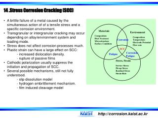
Conclusions • Stress Concentration on Tie-Rod Connector is not expected to be a problem. • Upper bracket and washer/tie-rod weld stress concentrations are potential hazards. • At current dimensions, the damper would require a Young’s Modulus of approximately 30,000 psi (Polyester Elastomer). • A more conventional rubber may be used with a smaller washer thickness.