Download
1 / 23
240 likes | 428 Views
In-situ Controlled Growth of Carbon Nanotubes by Local Synthesis. Researchers Takeshi Kawano and Michael Cho Advisor Professor Liwei Lin Berkeley Sensor & Actuator Center kawano@me.berkeley.edu. Outline. Background Motivation Experimental procedure

E N D
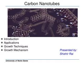
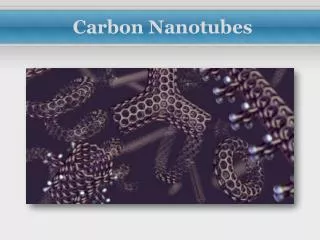
In-situ Controlled Growth of Carbon Nanotubesby Local Synthesis Researchers Takeshi Kawano and Michael Cho Advisor Professor Liwei Lin Berkeley Sensor & Actuator Center kawano@me.berkeley.edu
Outline • Background • Motivation • Experimental procedure • In-situ monitoring of CNT connection • Self-assembled single CNT • CNT/Si junction and contact resistance • Electrical properties of Si/CNT/Si system • “Carbon nanotube-based nanoprobe electrode” • Summary
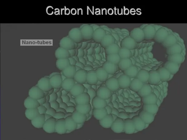
CNT-based nanomotor CNT-based bio-probe A. Zettl Gr., Nature, 424, 408 (2003) M. Lieber Gr., Nature, 394, 52 (1998). Nanotube oscillator IC integrated CNT P. L. EcEuen Gr., Nature, 431, 284 (2004). H. Dai Gr., Nano Letters, 4, 1 (2004) Background – Carbon nanotube –
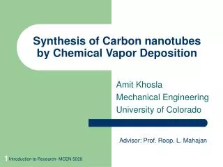
Motivation • CMOS integration of nano structures (carbon nanotubes (CNTs)) • Local and selective synthesis using silicon microstructures (MEMS) • Device applications to nano sensors and nano electronics • In-situ controlled growth of CNT • Assembly of single CNT • CNT/silicon contact discussed
Electric field assisted synthesis Temperature C2H2/Ar gas Synthesis pressure 850 ~ 900C 60 / 55 sccm 250 Torr Gaps between Si structures Bias between Si (V2 ) Electric field (V2 / gaps) 5 ~ 10 mm 2 ~ 5 V 0.2 ~ 1 V/mm Experimental Procedure Local synthesis of CNT
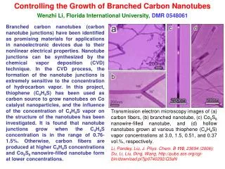
I-V Curves of Silicon/CNT/Silicon System 2.5 MW Nanotube Diameter 50nm Length 10.3mm
Outline • Background – Nanoprobe for cell/neuron – • Motivation • Biocompatible insulator for CNT • Process sequence • Images of CNT probes • Electrical properties of CNT probe Carbon Nanotube-based Nanoprobe Electrode
AFM with Nanoneedle I. Obataya, C. Nakamura, S. Han N. Nakamura, J. Miyake, Nano Letters, 5, 1 (2005). Multi-functional Probe S. Nagasawa, H. Arai, R. Kanzaki, I. Shimoyama, Proc. of Transducers’05, 1230 (2005). Properties of Neuron Diameter Neural Activity Extracellular Intracellular Frequency 5 ~ 10 mm 100 mV 100 mV DC10 kHz Background – Nanoprobe for cell/neuron – Microprobe devices for neuronal tissue From J. Donoghue, Nature Neuroscience, 5, pp1085 (2002)
Motivation • Carbon nanotube based nanoprobe electrode • Low invasive Intracellular probe for potential recording • Intracellular probe for chemical detector
CNT encapsulated with Parylene TEM image (50nm-thick Parylene) Biocompatible Insulator for CNT– Parylene-C – Parylene-C Properties & Characteristics • CVD(chemical vapor deposition) at Room temp. • High electrical resistivity (~1016W-cm) • Biocompatible material • Conformal fashion and pinhole free
SEM images (a) As-grown single CNT between silicon structures (b) After Parylene deposition, (c) After tip expose (d) Close-up view of the exposed tip in (c) Process Sequence Process sequence
TEM Image of CNT Probe TEM image of a single CNT Outside: 50-nm-thick Parylene-C. Inside: 10-nm-diameter CNT
Layout of MEMS structure for CNT probe Future Work “In-situ Controlled Growth of Carbon Nanotubes by Local Synthesis” • Contact issue ( metal contact with tungsten, gold electrode) • More real-time growth measurements • Investigation of the IC-compatibility “Carbon Nanotube-based Nanoprobe Electrode” • Impedance measurement of CNT probe • Penetration into cells (first with Onion cells) • Recording of biological signal from cell/neuron
Summary “In-situ Controlled Growth of Carbon Nanotubes by Local Synthesis” • In-situ controlled synthesis of CNT using MEMS structures Bias 2 ~ 5 V, gaps between Si structures 5 ~ 10 mm (E-field 0.2 ~ 1 V/mm) Instant of the CNT connection monitored (growth time is 8 ~ 50 seconds) Single CNT connection controlled by the in-situ monitoring system • Electrical properties of Si/CNT/Si system and CNT/Si junction CNT/Si contact resistance discussed with metal/Si junction model Overall resistance of the single CNT is 2.5 MW “Carbon Nanotube-based Nanoprobe Electrode” • Device concept proposed Carbon nanotube electrode for intracellular recording Low-invasive probe and low-damage to cell/neuron • Fabrication and experimental results Parylene-C deposited (50~100nm-thick), CNT tip exposed, I-V measured
CNT probe in chemistry and biology Background – Carbon nanotube – M. Lieber Gr., Nature, 394, 2 (1998). • chemically modified nanotube tips • detecting specific chemical and biological groups. Gas detection sensor Silicon MOS-compatibility NASA • SWNTs between two electrodes • Interaction between gas molecules and CNT. • Electrical signal observation, such as I or V. • Tested gases: NO2 , NH3 , etc. Y. Tseng, et al., Nano Letters, 4, 1 (2004). • SWNT • poly-Si inter connection • 875C CVD http://www.nasa.gov/centers/ames/research/technology-onepagers/gas_detection.html
I-V Curves of Silicon/CNT/Silicon System Properties of CNT Properties of CNT Number of CNTs Diameter Length Overall resistance 9 50 3 nm 8.8 mm (Average) 480 kW Number of CNTs Diameter Length Overall resistance 1 50nm 10.3 mm 2.5 MW
Layout of MEMS structure for CNT probe Future Work “In-situ Controlled Growth of Carbon Nanotubes by Local Synthesis” • Contact issue ( metal contact with tungsten, gold electrode) • More real-time growth measurements • Investigation of the IC-compatibility “Carbon Nanotube-based Nanoprobe Electrode” • Impedance measurement of CNT probe • Penetration into cells (first with Onion cells) • Recording of biological signal from cell/neuron
(a) (b) (c) (d) Self-Assembled Single CNTs Synthesis parameters Gaps Bias V1 Bias V2 8 mm 7.5 V 2.5 V
CNT :Work function of CNT Si: Electron affinity of silicon Eg-Si : Band gap of silicon Ei -EF : Fermi level for silicon Bp: Barrier height Bp=(S+Eg-Si ) -CNT = 0.37~0.67 eV CNT: multiwall CNT (root and tip growth) Si: p+type, conc. 1019/cm3 Contact resistance Specific contact resistivity C: 10-5~10-4W-cm2 [1] • Barrier height Bp:0.4 eV • Concentration of Silicon:1019 /cm3(p-type) Contact area A: 2 10 -11 cm2 • Diameter of CNT : 50nm Contact resistance = 0.5 ~ 5MW [1] K. K. Ng and R. Liu, IEEE Trans. ED, 37, 1535 (1990) CNT-Silicon Heterojunction
Electrical Properties of CNT Probe I-V measurement (a) Setup for the measurement (Au electrode) (b) SEM image of CNT (d) I-V curves of CNT (CNT: 22mm-length and 30nm-diameter)
Acknowledgements I would like to thank Lei Luo, Sha Li, Brian Sosnowchik for their insightful discussions, especially Brian’s contribution for the I-V measurement and voltage acquisition interface, and other Lab mates. And I would like to thank staff at the EML (Electron Microscopy Laboratory) at UC Berkeley, for their TEM work.