Download
1 / 32
320 likes | 349 Views
Learn about the reprogrammable Flash-based FPGAs used in the Data Processing Units for EUCLID mission instruments, ensuring radiation immunity and flexibility for critical functions. Design and flow details provided.

E N D
11/04/2018 SEFUW Reprogrammable Flash-based FPGA on EUCLID mission Raoul Grimoldi (OHB-I) Luca Sterpone (POLITO)
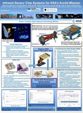
Euclid mission overview EUCLID is a cosmology mission part of Cosmic Vision 2015-2025 whose prime objective is to study the geometry and the nature of the dark Universe (dark matter, dark energy). The mission will investigate the distance-redshift relationship and the evolution of the cosmic structures by measuring shapes and redshifts of distant galaxies. EUCLID space segment will be a spacecraft placed into an orbit around L2 with a coverage of 15,000 deg2 in 6.25 years with step and stare observation strategy. Launch is planned for 2020. EUCLID spacecraft will host 2 instruments: • NISP (Near Infrared Spectrometer Photometer) • VIS (VISble imager)
Euclid mission : Instruments Data Processing Units OHB-I is in charge of the design of the Data Processing Units HW for both NISP and VIS as part of the Italian contribution to EUCLID mission • 1 CDPU unit for VIS • 2 DPU/DCU units for NISP NISP DPU/DCU units VIS CDPU unit
FPGA devices Both units make large use of functions implemented in FPGA devices
FPGA devices • Microsemi RTAX-S FPGAs are based on anti-fuse technology, widely used in space application in both NASA and ESA mission because of the high level of immunity to radiation effects : • SEL immune up to 117MeV/cm2/mg • TID better than 200Krad • F/F with TMR • Logic SEU better than 1E-10 upset/bit/day on GEO • Microsemi RT3PE3000L FPGAs are based on commercial flash technology that exhibit lower level of radiation effects immunity but is reprogrammable : • SEL immune up to 68MeV/cm2/mg • TID better than 30Krad (10% increase of propagation delay) • No SEU effects on configuration cell • D type F/Fs : Threshold 6 MeV-cm2/mg, saturated x-section 2E-7 cm2 per flip-flop
Design Flow for RTAX-S • Radiation Hardening of FPGA design in RTAX-S for mission like EUCLID requires very limited effort • EDAC on the internal SRAM in order to correct single errors • Internal memory scrubbing for long term storage memory area • Safe state machine • The design flow adopted in CGS is based on tailored ECSS-Q-ST-60-02C with the following steps
Design Flow for RT PROASIC Each DPU/DCU unit hosts 8 DCU boards, each board with 1 FPGA that implement • Reception of data stream on 8x parallel lines and pixel de-serialization • Buffering of the complete packet and CRC check • Extraction of TLM from scientific data • Coo-adding of pixels • Averaging and formatting of the coo-added frames before transmission to the memory board
Design Flow for RT PROASIC • On EUCLID mission, for the FPGA implementing the interface with the detectors system, the use of a reprogrammable FPGA has been preferred for the following reasons: • Request of “maximum flexibility” from the science team • Lack of knowledge of the real behavior of the interface of the SIDECAR : unexpected behavior may require mitigation in the FPGA not known at the time of design specification • Risk of late modifications required on the FPGA design : • in case of use of RTAX FPGA, 16 identical FPGAs mounted on the 2 DPU/DCU could be impacted with high schedule/cost impact • RTPROASIC will allow the modification of the design via JTAG without opening the DPU/DCU unit and changing the device
Design Flow for RT PROASIC • Radiation Hardening of FPGA design in RT PROASIC requires not negligible effort • EDAC on the internal SRAM in order to correct single errors • Internal memory scrubbing for long term storage memory area • Safe state machine • Radiation Hardening at RTL level • Radiation Hardening of the I/Os • TMR of F/Fs • SET effect evaluation • Gard Gates introduction for SET filtering
Design Flow for RT PROASIC The standard FPGA design flow is modified with the introduction of Radiation Mitigation activities • At RTL level • Implementation of local reset for the different functional blocks that can be reset before use by the SW or by the internal FPGA logic avoiding error accumulation • Implementation of independent controls for critical I/Os • Duplication of critical I/Os
Design Flow for RT PROASIC • Radiation Hardening of the I/Os • Identification of the criticality of the I/Os of the FPGA and need for mitigation • Estimation of the probability of error due to radiation effects on the I/Os in EUCLID environment • Mitigation definition : duplication or triplication of the I/O in different banks, external filtering, … • Compatibility with Signal integrity on the board • Compatibility with the available free pins on the FPGA
Design Flow for RT PROASIC The analysis has been performed with CREME using the cross sections derived from “New methodologies for SET characterization and mitigation of Flash based FPGAs”, TNS-00477-2007.R2. Predicted error rate due to the I/Os on EUCLID mission considering 16 FPGAs and implementation of the mitigation is
Design Flow for RT PROASIC Before CDR Radiation Hardening on netlist is implemented
Design Flow for RT PROASIC • Preliminary steps for RH are : • TMR on the F/Fs is implemented starting from the VHDL with synthesis tool Synplify • Place & Route of the FPGA is performed with Microsemi Designer • Static Timing Analysis • Functional verification with testbench on the post-layout netlist • Then the design database is provided to Politecnico of Torino for • SET analysis and GG insertion
SET mitigation flow on RT-PROASIC3 DCU VHDL netlist Synthesis Synplify • TMR on all the FFs is implemented starting from the VHDL with synthesis tool Synplify as baseline • Place & Route of the FPGA is performed with Microsemi Designer • Static Timing Analysis • Functional verification with test-bench on the post-layout netlist Place and Route Microsemi Libero SoC 11.8 Bitstream Static Timing Analysis Functional Verification
SET mitigation flow on RT-PROASIC3 DCU VHDL netlist Politecnico di Torino SEE-aware design flow Synthesis Synplify Verilog PDC DCU Guard Gate mitigated netlist Guard Gate mitigation Place and Route Radiation Profile Microsemi Libero SoC 11.8 SETA tool SET report AFL PDC Verilog Bitstream Static Timing Analysis • SET analysis performed on the original netlist • Radiation mission profile includes SETs between 0.42 and 0.49 ns • Radiation exposure during the mission is estimated as 4 Krad • Guard gate mitigation is applied selectively at the input of TMR FFs Functional Verification
SET analysis tool and Guard Gate mitigation • The SET analysis is performed by the SETA tool • SETA is an EDA software tool that evaluates the impact of SETs on the circuit functionality • It calculates the SET propagation in all the circuit nodes • It identifies the maximal SET pulse width at the input of each Flip-Flop 0.436ns 0.4 ns 0.952 ns
SET analysis tool and Guard Gate mitigation • Guard Gate mitigation is a software tool (named PDTmite) that automatically inserts a guard gate structure at the input of a Flip-Flop candidate to SET filtering • The filtering delay is generated on the basis of the SET report • Designer can tune the filtering capabilities 0.9 ns SET filter
SET mitigation flow on RT-PROASIC3 - Summary • Resource and static timing analysis of the EQM_TMR original netlist with TMRed Flip-Flops (by OHB Italia) • SETA analisys and evaluation of the SET pulse report • (I) Guard Gate mitigation insertion with 1.4 ns maximal broadening reduction • Area over-head around 8% - Timing closure failed on 30 MHz clock domain • (II) Guard Gate mitigation insertion with 1.2 ns maximal broadening reduction • Area over-head around 3.8% - Timing closure failed on 30 MHz clock domain • (III) Guard Gate mitigation insertion with 1.0 ns maximal broadening reduction • Area over-head around 1.4% - Timing closure successful. • SET analysis and evaluation of the EQM_TMR_GG netlist with guard-gate mitigation • SET maximal pulse width reduction from 3.2 ns to 1.9 ns • Functional verification successful (by OHB Italia)
SET mitigation flow on RT-PROASIC3 - Step 1 • Original netlist EQM_TMR with TMRed Flip-Flops • Usedresource area on the A3P3000RT is 63.65% • Static timing analysis of the EQM_TMR netlist at 4 Krad of radiation exposure
SET mitigation flow on RT-PROASIC3 – Step 2 • Single Event Transient Analysis of the EQM_TMR netlist • Propagation of source SET pulse from all the circuit sensitive nodes • Storage of SET pulse width at the input of each Flip-Flop • Comparison of the maximal SET pulse width of each FF versus the source SET
SET mitigation flow on RT-PROASIC3 – Step 2 Maximal pulse with per FF Maximal SET pulse width [ns] 0.43ns SET Pulses are not broadened but partially filtered Flip-Flop [#] • Original not mitigated (guard gate) SET distribution • SET pulse width has a broadening effect between 0.5 and 3.2 ns
SET mitigation flow on RT-PROASIC3 – Steps 3, 4 and 5 • Exhaustive filtering mitigation requires 45,261 tiles which exceeds available area • Filtering of 1.4ns on mostcriticalFlip-Flops as reasonable point to achieve area and timing closure • Three iterations of the guard gate mitigation tool, implementation and timing analisys have been made • Mitigated netlist EQM_TMR_PDT with TMRed Flip-Flops and Guard Gate (1.4% area overhead)
SET mitigation flow on RT-PROASIC3 – Step 6 • Single Event Transient Analysis of the EQM_TMR_PDT netlist • Maximal SET pulse width has been reduced to 1.9 ns • Application of placement constraints for the selected FFs guard gates • Overall reduction of SET pulse width to 0.2 and 1.9ns maximal SET pulse width
SET mitigation flow on RT-PROASIC3 – Step 6 Relevant to the EUCLID space mission radiationenvironment Maximal SET pulse width [ns] Flip-Flop element SET pulsesbelow 0.4 ns will be electrically filtered by the FF inputs
SET mitigation flow on RT-PROASIC3 – Step 6 • Single Event Transient mitigation comparisons between pre-filtered netlist EQM_TMR and the guard-gate filtered netlist EQM_TMR_PDT relevant for the mission profile • Removal of 97% of the broadened SETs • Remaining 3% have reduced pulse width • 3.2 ns versus 1.9 ns max SET width • 70% of the EQM_TMR broadened SET pulses became totally filtered
Conclusions • SEE-aware tool flow including the Single Even Transient analyzer (SETA) and the Guard-Gate mitigation (PDTmite) has been effectively applied • Nowadays a version is available with a user friendly Graphic User Interface • Results show an effective reduction of the SET phenomena but limited by the design timing closure • Mitigation of the SETs were flexibly tuned with respect of the design timing characteristics • However, a complete SET mitigation was not applicable due to timing closure • SET filtering methodsrequires timing margin • Further study of SET filtering methods not including delay penalty are requested OHB Italia S.p.A. / Title of the presentation / Date
Conclusions • Thank you! OHB Italia S.p.A. / Title of the presentation / Date
Spare slides SET comparison OHB Italia S.p.A. / Title of the presentation / Date
Design Flow for RT PROASIC • Radiation Hardening of the I/Os • Identification of the criticality of the I/Os of the FPGA and need for mitigation • Estimation of the probability of error due to radiation effects on the I/Os in EUCLID environment • Mitigation definition : duplication or triplication of the I/O in different banks, external filtering, … • Compatibility with Signal integrity on the board • Compatibility with the available free pins on the FPGA