Download
1 / 20
200 likes | 319 Views
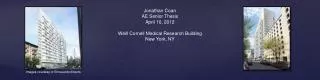
Jonathan Coan AE Senior Thesis April 10, 2012 Weill Cornell Medical Research Building New York, NY. Images courtesy of Ennead Architects. Presentation Outline Introduction Existing Structure Thesis Goals Structural Depth Enclosure Breadth Conclusion. Presentation Outline Introduction

E N D
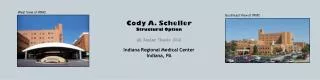
Jonathan Coan AE Senior Thesis April 10, 2012 Weill Cornell Medical Research Building New York, NY Images courtesy of Ennead Architects
Presentation Outline • Introduction • Existing Structure • Thesis Goals • Structural Depth • Enclosure Breadth • Conclusion
Presentation Outline • Introduction • Existing Structure • Thesis Goals • Structural Depth • Enclosure Breadth • Conclusion • General Building Data • Building Name: Weill Cornell Medical Research Building • Location: 413 East 69th Street, New York, NY 10021 • Occupant: Weill Cornell Medical College • Occupancy Type: Laboratory/Research facility • Size: 455,000 square feet • Number of Stories: Below Grade – 3 • Above Grade – 18 + penthouse • Dates of Construction: 2010 – 2014 • Overall Cost: $650 Million • Delivery Method: Design-Bid-Build • Project Team • Architect: Ennead Architects • Structural Engineer: Severud Associates • Mechanical Engineer: Jaros Baum & Bolles • Laboratory Consultant: Jacobs Consultancy GPR • Construction Manager: Tishman Construction
Presentation Outline • Introduction • Existing Structure • Thesis Goals • Structural Depth • Enclosure Breadth • Conclusion • Existing Foundation • Spread footings on undisturbed bedrock • Slab on grade 6” resting on 3” mud slab on 24” of crushed stone • Water table uplift an issue • (4) 50 ton rock anchors Basement Floor Plan
Existing Floor System • 2-Way Flat Plate Slab • Typical thickness: 12.5” • Cantilever in front, 9’-8” • Slab cambered 5/8” for deflections • Vibrations • Laboratories sensitive to vibrations • Floors limited to 2000 micro-inches per second • HSS members on alternate floors to tie slabs together vibrationally Typical Floor Plan
Presentation Outline • Introduction • Existing Structure • Thesis Goals • Structural Depth • Enclosure Breadth • Conclusion • Thesis Goals • Structural Depth • Redesign floor system • Eliminate camber • Minimize floor-to-floor heights • Satisfy deflection requirements • Column Investigations • Change size of 14 x 72 columns • Remove Row B columns • Enclosure Breadths • Redesign Brick Cavity Wall system • Conduct heat transfer and moisture analysis for comparison of enclosure systems (Mechanical) • Compare architectural features of each system (Architecture) • MAE Course Related Study • Information, methods, and tools from AE 542 (Building Enclosure Science and Design) used for enclosure breadths
Presentation Outline • Introduction • Existing Structure • Thesis Goals • Structural Depth • Enclosure Breadth • Conclusion • Structural Depth • Floors Used for Redesign • 3 – 16 structurally identical = Typical Floor • 17th Floor • 18th Floor • Other Parameters • f’c = 4000 psi • Banded Beam System • Uniform one-way slab with thickened portion called “band-beam” • Span Conditions: • Typical Span of Typical Floor • End Span of Typical Floor • Higher Load Areas of Typical Floor • 17th Floor • 18thFloor • Reinforcement: Grade 250 Seven-wire Strands
One-Way Prestressed Slab • Pre-stress losses assumed to be 15% • L/45 used for initial thickness Banded Beam System • Band-Beams • Width: 6ft • Bundles of (12) 3/8” strands
Process • RAM Concept • 10” slab thickness • Bundles of (12) 1/2” strands • Minimum clear cover top and bottom: 1.5” • Latitude and Longitude prestressing Two-Way PT Flat Plate Slab Typical Floor Plan 17th Floor Plan 18th Floor Plan
Typical Floor: Mmax = 500 kip-ft Two-Way PT Flat Plate Slab Maximum Moments 17th Floor: Mmax = 850 kip-ft 18th Floor: Mmax = 1000 kip-ft
Typical Floor: Δmax = .225 in Two-Way PT Flat Plate Slab Deflections 17th Floor: Δmax = .24 in 18th Floor: Δmax = .24 in
14 x 72 Column • Not just a column, not quite a wall • Works well with floor plan layout • Column Investigations • Removal of Column Row B • New Column design: • Original Column A3 • 44 x 20, (16) # 9 bars • Pu = 1555 kips • New Column A3 • 48 x 24, (16) #11 bars • Pu = 2518 kips, ΦPn = 3464 kips • Original Column C3 • 36 x 24, (16) #7 bars • Pu = 1520 kips • New Column C3 • 42 x 28, (16) #11 bars • Pu = 2493 kips, ΦPn = 3517 kips Partial Floor plan of cantilever
Banded Beam Effects on Floor Systems Two-Way PT Flat Plate Slab 17th Floor Typical Floor 18th Floor
Structural Depth Summary • Floor System Redesign • Both systems meet design criteria • Two-way PT Flat Plate better alternative • No camber necessary • Floor-to-floor heights reduced • Less concrete used • Column Investigations • 14 x 72: Don’t change • Remove Row B: Not feasible
Presentation Outline • Introduction • Existing Structure • Thesis Goals • Structural Depth • Enclosure Breadth • Conclusion Enclosure Breadth Glass Sunshade Curtain Wall View: Front of the building looking up Images courtesy of Ennead Architects
Layers • 4” brick (Roman) • 3” air space • 3” rigid insulation (expanded) • Air barrier • Vapor barrier • 8” concrete wall Brick Cavity Wall Heat Transfer Moisture Analysis Winter Summer
Layers • 1.25” EIFS • 2” air space • 2.5” rigid insulation (extruded) • Air barrier • Vapor barrier • 6” CMU EIFS Wall Heat Transfer Moisture Analysis Winter Summer
Enclosure Breadth Summary • Success of Redesign • Thinner, lighter system • Decrease heat loss and gain • Decrease potential for condensation in the air space EIFS Wall (Winter) Brick Cavity Wall (Winter)
Presentation Outline • Introduction • Existing Structure • Thesis Goals • Structural Depth • Enclosure Breadth • Conclusion • Conclusions • Structural Depth • Two floor systems examined • Two-Way PT Flat Plate slab deemed best alternative to original design • Eliminate camber • Minimize floor-to-floor heights • Satisfy deflection requirements for cantilever • Column Investigations • Change size of 14 x 72 columns • Remove Row B columns • Original column layout is best • Enclosure Breadths • EIFS Wall system designed • New design compared with original Brick Cavity Wall system • More insulating, less heat loss/gain • Better for moisture control
Acknowledgements Severud Associates Steve Reichwein Janice Clear Brian Falconer Ennead Architects Paul Stanbridge The Pennsylvania State University Dr. Thomas Boothby – Thesis Advisor Professors M. Kevin Parfitt and Robert Holland Dr. Linda Hanagan – Academic Advisor I was also like to thank my friends and family, without whom I wouldn’t be where I am or who I am today. Questions and Comments Thank You