Download
1 / 25
250 likes | 389 Views
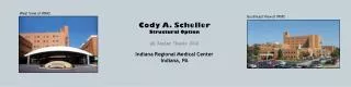
West View of IRMC. Southeast View of IRMC. Cody A. Scheller Structural Option AE Senior Thesis 2012 Indiana Regional Medical Center Indiana, PA. West View of IRMC. Presentation Outline Introduction Existing Structure Thesis Goals Structural Depth Lighting Breadth Conclusion

E N D
West View of IRMC Southeast View of IRMC Cody A. Scheller Structural Option AE Senior Thesis 2012 Indiana Regional Medical Center Indiana, PA
West View of IRMC Presentation Outline Introduction Existing Structure Thesis Goals Structural Depth Lighting Breadth Conclusion Questions & Comments Southeast View of IRMC
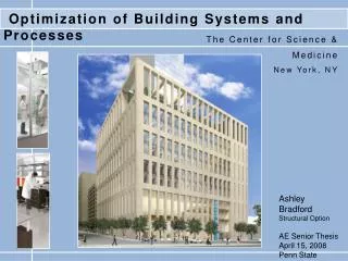
Arial View of IRMC • Project Information • Location: Indiana, PA • Occupancy Type: Full-Service Medical Center • Size: 140,000 SF • Height: 97 Feet Presentation Outline Introduction Existing Structure Thesis Goals Structural Depth Lighting Breadth Conclusion Questions & Comments N
Arial View of IRMC • Project Information • Owner: Not Released • Architect: Rea, Hayes, Large, & Suckling • Engineer: Rea, Hayes, Large, & Suckling • Tenant: Indiana Regional Medical Center Presentation Outline Introduction Existing Structure Thesis Goals Structural Depth Lighting Breadth Conclusion Questions & Comments N
Existing Structure • Foundation • T-Shaped Foundation • 16-inch concrete footings • Concrete Piers • 32-inch • Corners of foundation • Anchor Bolts Presentation Outline Introduction Existing Structure Thesis Goals Structural Depth Lighting Breadth Conclusion Questions & Comments Example Anchor Bolt
Existing Structure • Gravity System • Bay Size: 26’-0’’ x 16’-0’’ • Completely Symmetrical • 5 ½’’ Composite Floor Construction • W16x50 Fill Beams • W14x38 Girders • W14 Columns • 78 to 111 lb/ft Presentation Outline Introduction Existing Structure Thesis Goals Structural Depth Lighting Breadth Conclusion Questions & Comments Example Floor System Diagram
Existing Layout • Existing Structure • Lateral System • Braced Frame • Steel Moment Frame Presentation Outline Introduction Existing Structure Thesis Goals Structural Depth Lighting Breadth Conclusion Questions & Comments N
Thesis Goals • Structural Depth • Redesign building with concrete • Retain current floor plan • Design for additional renovations • Lighting Breadth • Determine effect on lobby/waiting room • Redesign basic lighting system Presentation Outline Introduction Existing Structure Thesis Goals Structural Depth Lighting Breadth Conclusion Questions & Comments
Presentation Outline Introduction Existing Structure Thesis Goals Structural Depth Lighting Breadth Conclusion Questions & Comments ETABS Model • Structural Depth • Design Process • Initial Plan Layout • Gravity System Design • Lateral System Design N
Two-Way Post-Tensioned Two-Way Flat Plate Presentation Outline Introduction Existing Structure Thesis Goals Structural Depth Lighting Breadth Conclusion Questions & Comments • Structural Depth • Slab Design Alternatives • Two-Way Flat Plate System • Two-Way Post-Tensioned Slab • Precast Hollow Core Planks Hollow Core Planks
Structural Depth • Two-Way Flat Plate Design • 9’’ uniform Slab Thickness • L/h = 33 • Typical span length of 26’-0’’ • 80 psf Live Load • 30 psf Superimposed Dead Load • Roof Slab = 12’’ thickness • No Drop panels or interior beams Presentation Outline Introduction Existing Structure Thesis Goals Structural Depth Lighting Breadth Conclusion Questions & Comments Two-Way Flat Plate System
ETABS Model • Structural Depth • Two-Way Flat Plate Design • 8 spans at 26’-0’’ each in N/S Direction • 6 spans at 16’-0’’ each in E/W Direction • Slab Reinforcement • Top Bars = Negative Moments • Bottom Bars = Positive Moments Presentation Outline Introduction Existing Structure Thesis Goals Structural Depth Lighting Breadth Conclusion Questions & Comments
Frame B – 26’-0’’ Span • Structural Depth • Slab Reinforcement – Frame B • Column Strip – 8 ft width • 12 - #6 Top Bars - @ 10.6’’ o.c. • 6 - #6 Bottom Bars - @ 12’’ o.c. • Middle Strip – 18 ft width • 12 - #6 Top Bars - @ 15.4’’ o.c. • 12 - #6 Bottom Bars - @ 15.4’’ o.c. Presentation Outline Introduction Existing Structure Thesis Goals Structural Depth Lighting Breadth Conclusion Questions & Comments Middle Strip Column Strip
Frame A – 16’-0’’ Span • Structural Depth • Slab Reinforcement – Frame A • Column Strip – 8 ft width • 8 - #6 Top Bars - @ 6.86’’ o.c. • 6 - #6 Bottom Bars - @ 12’’ o.c. • Middle Strip – 8 ft width • 6 - #6 Top Bars - @ 12’’ o.c. • 6 - #6 Bottom Bars - @ 12’’ o.c. Presentation Outline Introduction Existing Structure Thesis Goals Structural Depth Lighting Breadth Conclusion Questions & Comments Middle Strip Column Strip
Structural Depth • Column Design • Uniform Size throughout building • 20’’ x 20’’ columns • Column Height: 13’-0’’ to 14’-0’’ • Reinforcement: • 8 #9 bars vertically • #3 ties every 16’’ Presentation Outline Introduction Existing Structure Thesis Goals Structural Depth Lighting Breadth Conclusion Questions & Comments
Presentation Outline Introduction Existing Structure Thesis Goals Structural Depth Lighting Breadth Conclusion Questions & Comments ETABS Model • Structural Depth • Lateral System Design • Shear Wall Design • Thickness: 16’’ • Placed according to braced frames N
Structural Depth • Overturning • Building Weight: 26,000 kips • Seismic Base Shear: 650 kips • Wind Base Shear N/S: 519.18 kips • Wind Base Shear E/W: 969.54 kips • Seismic Load: 2.5% of Dead Load • Wind Load: Overturning Moment is less than Resisting Moment Presentation Outline Introduction Existing Structure Thesis Goals Structural Depth Lighting Breadth Conclusion Questions & Comments
Structural Depth • Lateral System Deflections • Seismic Controlled in North/South • Wind Controlled in East/West • Drift • E/W Drift Due to Wind = 0.95’’ • N/S Drift Due to Seismic = 0.113’’ Presentation Outline Introduction Existing Structure Thesis Goals Structural Depth Lighting Breadth Conclusion Questions & Comments • Lateral System Deflections Continued • Max. Allowable Seismic Story Drift • 0.14’’ – 14 ft floor height – 0.010hsx
Lighting Breadth • Current Design • Lobby/Waiting Room • Room Dimensions: 20’-0’’ x 30’-0’’ • Room Height: 11’-0’’ • Recessed Fluorescent Lighting • New Design Changes • Room Height: 12’-0’’ • LED Lighting Recessed Fluorescent Luminaire Presentation Outline Introduction Existing Structure Thesis Goal Structural Depth Lighting Breadth Conclusion Questions & Comments
Lighting Breadth • Design Criteria • Target Illuminance: 10 fc – 20 fc • CCT: neutral & warm • CRI: 70 or higher • Specific Tasks • Aesthetics • Light Distribution: Direct Presentation Outline Introduction Existing Structure Thesis Goal Structural Depth Lighting Breadth Conclusion Questions & Comments
Lighting Breadth • Luminaire Selection • 6’’ LED Downlight • One 31 Watt Lamp Fixture • Installed in ceiling cavity • Lumen Method • 14.2 footcandles with LLFs • 12 Luminaires 6’’ LED Downlight Presentation Outline Introduction Existing Structure Thesis Goal Structural Depth Lighting Breadth Conclusion Questions & Comments Luminaire Layout
Lobby/Waiting Room Photo Presentation Outline Introduction Existing Structure Thesis Goal Structural Depth Lighting Breadth Conclusion Questions & Comments • Lighting Breadth Conclusion • New Design • Convenience • Functionality • Aesthetics
Conclusions The redesign of the structural system from steel to concrete was effective, but not as efficient. Symmetry of the building plan was preserved. Foundation system would need redesigned from the effects of the new building weight. Change in floor-to-floor heights will result in new lighting designs in some areas. Presentation Outline Introduction Existing Structure Thesis Goal Structural Depth Lighting Breadth Conclusion Questions & Comments
Acknowledgments • Indiana Regional Medical Center • Norman Ziemer – Facility Engineer • Samuel Baker – Administration • The Pennsylvania State University • Dr. Linda Hanagan – Faculty Advisor • M. Kevin Parfitt - Professor • Robert Holland – Professor • All AE Faculty & Staff • AE Class of 2012
West View of IRMC Southeast View of IRMC Questions & Comments