Download
1 / 17
170 likes | 280 Views
Introduction Part 3: Input/output and co-processors. dr.ir. A.C. Verschueren Eindhoven University of Technology Section of Digital Information Systems. What IS communication?. For a computer to do any useful work, it must communicate with its surroundings

E N D
IntroductionPart 3: Input/output and co-processors dr.ir. A.C. VerschuerenEindhoven University of TechnologySection of Digital Information Systems
What IS communication? • For a computer to do any useful work,it must communicate with its surroundings 'Communication' consists out of two things 1) Information transfer 2) Synchronisation • These may be present in variable amounts,from pure (continuous) information transferto pure synchronisation • First, clear a common misconception... no user interfaceno communication
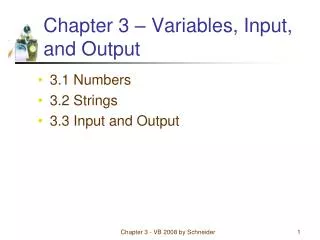
0 input port data data read read input 1 output port CPU write select addr data write output address 4 select 0 address 1 data 'real' 4..7 decoder select memory addr read memory 7 write addr ‘Memory mapped’ input/output • Addresses in memory space are used to access the I/O ports with normal memory read/writes • More ports possible by extra address decoding
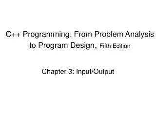
data data input in read out CPU read data output write write addr data read memory write addr Separate input/output (address) space • The CPU uses extra control signals (and special instructions) to access input and output ports • More ports possible by adding control signals orby using the address bus to encode port addresses
Ports and synchronisation • Input ports transfer data to the processor data bus • Output ports 'latch' (remember) the data provided by the processor between output accesses • Synchronisation of data transfer can be done • Use separate output port bits as synchronisation signal • Use read/write/in/out signals for synchronisation • Receiving synchronisation signals via input port bits is very time consuming: they need continuous checking
Receiving synchronisation signals • It is much better to let the synchronisation signal itself inform the CPU that it has become activated ! • Add hardware to the CPU which 'listens' to a synchronisation signal • When activity is detected, this hardware... 1) Stops whatever the CPU was doing 2) Handles the synchronisation signal by calling a subroutine • At return from this subroutine, the program which was running is continued as if nothing has happened • This forms the basis of the 'interrupt' mechanism • The subroutine started by the hardware is called'interrupt routine'
Basic interrupt hardware and operation • An input pin on the CPU is checked at the end of handling each instruction • The PC is saved and a JUMP (to a specific address) is performed if this pin is found to be active • At the end of the interrupt routine, the PC must be restored to continue with the interrupted program • The interrupt routine should not modify storage locations (memory AND registers) used by this program …unless they form the communication medium between the interrupt routine and the program !
Saving & restoring PC and other registers • Use separate register sets for the main program and the interrupt routines • Limited number of interrupts, no recursion possible • Extremely fast switching, interrupt 'tasks' possible • Save register set in fixed memory locations • Much slower switching, no recursion possible • Simple hardware if most of work done in software • Save register set on the stack • Still slow in switching • Recursion possible, can use existing hardware (for CALL, RET, PUSH, POP)
Where to start the interrupt routine ? • At hardware-fixed locations in program memory • Very inflexible, number of interrupts limited • Relatively simple hardware • External logic provides start address (input port) • Complex hardware outside the CPU • Can be very flexible, simple hardware in CPU • Use a table in memory indexed by interrupt nr. • Special hardware in CPU (moderate complexity) • Reasonable flexibility, efficiency and speed
Importance of interrupts • Not all interrupts are equally important 1) Interrupt routines may not be interrupted by less important ones • If a less important interrupt occurs, this must be remembered so that its routine can be started a.s.a.p. 2) Interrupt routines must be interruptable by more important ones • Most CPU’s automatically disable ALL interrupts when an interrupt routine is started We need much ‘finer’ control than that !
Remembering, masking & prioritising • Hardware should remember an interrupt’s occurrence until it is actually handled • May be part of I/O synchronisation hardware • Must be possible to 'mask' (disable) interrupts individually • Software controlled mask bits via an output port • Mask bits can be controlled completely by hardware • Hardware should 'prioritise' interrupts to select the most important non-masked one Possible, but very slow in software !
‘Traps’: interrupts from within the CPU • Generated when instructions encounter an error • Arithmetic errors, f.i.: overflow, divide by zero • These traps can be seen as the hardware basis for 'exceptions' • Hardware errors, f.i.:memory fault, accessed device does not respond • Traps and interrupts have some small differences • During trap handling, most interrupts remain enabled • A trap handler is an extension of the running program • The trapped instruction will in general be re-started following the trap handling routine This is sometimes very difficult !
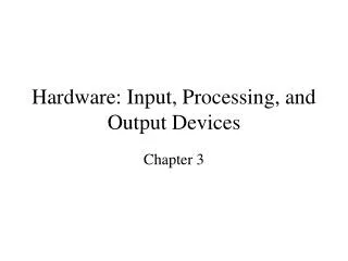
DMArequest DMArequest request DMAgrant DMAgrant read read grant I/OHW write write CPU data data CPU has bus address address CPU releases memory I/O HW has bus CPU takes bus back Reducing I/O handling time even further • Interrupts still require a lot of software (= time!) to move data between memory and a port • Save time by allowing I/O hardware to access memory directly, without assistance of the CPU This is called 'Direct Memory Access' (DMA)
The ‘intelligence’ of DMA • DMA can be used to create and/or read complex data structures without bothering the CPU • This requires a lot of 'intelligence' in the I/O hardware • Still requires an interrupt to signal the main program • Concurrent I/O needs multiple DMA 'channels’ • Same functionality needed as for handling multiple interrupts (remembering, masking and prioritising) But this time, it has to be all in hardware !
Co-processors: divide and conquer • A ’co-processor' is hardware which takes over (software) functions from the main CPU This increases the speed of the system as a whole • The CPU has fewer functions to perform • Co-processors can use customised (fast) hardwareinstead of standard hardware running software • Co-processors should not bother the CPU • Use DMA to transfer data, commands and results • Use interrupts to signal important things onlyinterrupts may run in both directions !
’Loosely coupled' co-processors • Have no connection with main CPU instructions • May even execute their own programs ! • Commanded by explicit I/O actions from the CPU or command blocks in memory (with an ‘attention’ signal) • Returns results through memory or explicit I/O actions after interrupting the main CPU Used to off-load complete I/O related tasks from the main CPU(for instance the device drivers in an O.S.) Also used to speed complex data processing tasks if theco-processor contains better hardware than the CPU
’Closely coupled' co-processors • Keep track of instructions executed by main CPU • Are actually controlled by these instructions • Some instructions are treated as 'no-operation' by main CPU • These trigger the co-processor to start a specific operation • Data transfer is done with DMA • The address may be provided by main CPU using a 'dummy' read cycle during execution of the 'no-operation' instruction • Result codes transferred with DMA or special I/O ports • Synchronisation is absent or uses special hardware Used to extend the main CPU instruction set (f.i. floating point)