Download
1 / 14
140 likes | 350 Views
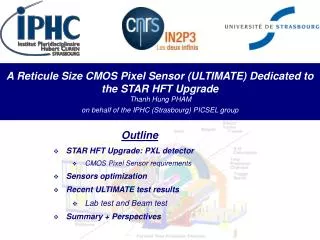
A Reticule Size CMOS Pixel Sensor (ULTIMATE) Dedicated to the STAR HFT Upgrade Thanh Hung PHAM on behalf of the IPHC (Strasbourg) PICSEL group. Outline STAR HFT Upgrade: PXL detector CMOS Pixel Sensor requirements Sensors optimization Recent ULTIMATE test results Lab test and Beam test

E N D
A Reticule Size CMOS Pixel Sensor (ULTIMATE) Dedicated to the STAR HFT UpgradeThanh Hung PHAM on behalf of the IPHC (Strasbourg) PICSEL group Outline • STAR HFT Upgrade: PXL detector • CMOS Pixel Sensor requirements • Sensors optimization • Recent ULTIMATE test results • Lab test and Beam test • Summary + Perspectives
~1 mm ~300 µm ~250 µm <30 µm PXL vertex TPC SSD IST Heavy Flavor Tracker (HFT) at STAR • HFT is an upgrade of the inner tracking system of STAR detector comprising : • SSD – Silicon Strip Detector • IST – Inner Silicon Tracker • PXL – Pixel Detector (2 layers at 2.5 & 8 cm) • Physical Goals : Identification of mid rapidity Charm and Beauty mesons and baryons through direct reconstruction and measurement of the displaced vertex with excellent pointing resolution ~ 150 µm IPHC hung.pham@ires.in2p3.fr
PIXEL SENSORS FOR HFT Sensors Requirements • Multiple scattering minimisation: • Sensors thinned to 50 µm, mounted on a flex kapton/aluminum cable X/X0 = 0.37% per layer • Sufficient resolution to resolve the secondary decay vertices from the primary vertex • < 10 µm • Luminosity = 8 x 1027 / cm² / s at RHIC_II • ~200-300 (600) hits / sensor (~4 cm2) in the integration time window • Short integration time ~< 200 µs • Low mass in the sensitive area of the detector airflow based system cooling • Work at ambient (~ 35 °C ) temperature • Power consumption <~ 150 mW / cm² • Sensors positioned close (2.5 - 8 cm radii) to the interaction region • ~ 150 kRad / year • few 1012 Neq / cm² / year carbon fiber sector tubes (~ 200µm thick) Aluminum conductor Ladder Flex Cable Ladder with 10 MAPS sensors (~ 2×2 cm² each) Insertion from one side 2 layers 10 sectors 4 ladders/sector Leo Greiner @ St Odile CMOS Workshop, Sep 2011 IPHC hung.pham@ires.in2p3.fr
Main characteristics of ULTIMATE (Mimosa-28) sensor • 0.35 μm process with high-resistivity epitaxial layer • column // architecture with in-pixel CDS & amplification • end-of-column discrimination and binary charge encoding, followed by zero suppression logic • active area: 960 columns of 928 pixels (19.9×19.2 mm²) • pitch: 20.7 μm ~0.9 million pixels charge sharing >~ σsp 3.5 μm expected • tr.o. ≤ 200 μs ( ~ 5×10³ frames/s) suited to >106 part./cm²/s • 2 outputs at 160 MHz • ≤ 150 mW/cm² power consumption • Radiation tolerant (~150 kRad/year & 3x10¹² neq/cm²) • Submitted by end-January 2011 • Received early April 2011 IPHC hung.pham@ires.in2p3.fr
Main characteristics of ULTIMATE (Mimosa-28) sensor (suite) Based on expertise's acquired from M26 chip for EUDET, the design of ULTIMATE has been optimized for STAR environment 8 analog outputs (Test purpose only) Pixel Optimization: Radtol ~ 150 kRad/year & 3x10¹²Neq/cm²/year Consumption < 150mW/cm2 Large reticule size (~2cmx2cm) Row sequencer Minimize the delays of signals over ~2cm Pixels Ref Regulator &Analog Power Supply regulator (Optional) Reduce I/O pads Programmable (Ref Regulator) End-column 960 discriminators: Offset compensation Encoding & Zero suppression logic: STAR conditions Bias current & Ref DACs High data size & Rate: 2 Memories 2048x32-bits 2 Outputs at 160 MHz I/O Pads: Powers, LVDS & Controls JTAG Configuration PLL (Optional) IPHC hung.pham@ires.in2p3.fr
M9 Pixel optimization • Radiation Tolerant and Power Consumption • Enclosed layout transistor M4 • Tradeoff between Power Consumption and Radiation Tolerant -> Optimization of pixels size (20.7x20.7µm²) • ~2x2cm2 reticule size • Multiplex pixels output to reduce the capacitance of output nodes • Optimization of output buffer stage (transistors M7, M8 & M9) in order to drive 2cm of metal line R ~ 1.9 KΩ C ~ 4 pF ~50µA ~3µA Out group Select_Gr IPHC hung.pham@ires.in2p3.fr
Digital conception challenges • 2cm of row controls signal • Row sequencer logic : Uniformly distributed with dispersion < 500ps • Optimization of zero suppression to cope with STAR environment • Up to 9 states /row • Segmented by 15 groups of 64 columns -> Symmetrical distributions of digital controls over ~2cm (at 50MHz) • High density & High speed readout :~0.9 Mpix & < 200µs frame readout • 2 memories of 2048x32 bits • 2 outputs of 160MHz • Increase frequency up to 160MHz • Layout constraint : 2261µmx19872µm • The output of SRAM is serialized at 160MHz 19295µm 250µm Row sequencer IPHC hung.pham@ires.in2p3.fr
On-chip Regulators • Internal Pixel References Voltages Vcl Integrated VCL Regulator Reduce crosstalk between sensors Reduce material budget: no extra decoupling capacitors Ultimate ~2x2cm² Ladder of 10 Ultimate sensors using external Vcl Crosstalk between sensors through Vclp Size 0.0389 mm² Capacitive Load > 5nF Consumption < 1mW Output range 1.9-2.3V Noise 74.8 nV/√Hz @ 1 kHz PSRR 52 dB @ 10 kHz 38 dB @ 1 MHz IPHC hung.pham@ires.in2p3.fr
LAB TEST RESULTS • Analogue output noise (Mode Test): • Conditions: • Pixel array scan at 40MHz • T = 20°C • Nominal JTAG load • Analog Power Supply (VddA) = 3.3V ENC ~ < 15 e- (On-chip reference regulator) Gain ~ 65µV/e- Good Noise uniformity The CCE is very little sensitive to Temperatureand Analog Power Supply variations • Charge Collection Efficiency (Mode Test): IPHC hung.pham@ires.in2p3.fr
Scan of matrices pixel and discriminator Sub-matrix A Sub-matrix A IPHC hung.pham@ires.in2p3.fr
Beam Test Results (July 2011) • Conditions: • CERN-SPS 120 GeV π− beam • BT made of 6 Ultimate sensors(20µm thick epi) • T = 20°C & 30°C • ionizing radiation dose: 0&150 kRad • Analog power supply : 3V & 3.3V • Results: • Efficiency > 99.5 % with a fake hit rate << 10-4 • Spatial resolution < 4 µm IPHC hung.pham@ires.in2p3.fr
Conclusion & perspectives • ULTIMATE sensors for the PXL detector of STAR HFT experimenthas been designed and tested in 2011 • The lab test and beam test showed : • Robust regarding temperature variations • Operational with analog power supply down to 3V • High detection efficiency ( > 99%) with very low fake event of beam test • High yield : > 90% • 12 sensors fully functional • 4 with 1% of death pixels • The Ultimate sensor fulfils all STAR HFT specifications • Engineering run of ULTIMATE sensor (12 wafers) is being submitted in September for equipping the engineering prototype detector • Start of run at RHIC in FY 2012 • The ULTIMATE sensor development allows to accumulate expertises for future sensor designs (ALICE, AIDA, CBM, EIC, …) IPHC hung.pham@ires.in2p3.fr
BACKUP SLIDES IPHC hung.pham@ires.in2p3.fr
MIMOSA26 with high resistivity EPI layer (1) • Charge collection efficiency for the seed pixel, and for 2x2 and 3x3 pixel clusters • Signal to noise ratio for the seed pixel before irradiation and after exposure to a fluence of 6 x 10¹² neq / cm² Christine HU@TWEPP 2010 IPHC hung.pham@ires.in2p3.fr