Lecture 6. Adders
ECM585 Special Topics in Computer Design. Lecture 6. Adders. Prof. Taeweon Suh Computer Science Education Korea University. Introduction. So far, we have discussed the basic skill of designing combinational and sequential logic using schematic and Verilog-HDL

Lecture 6. Adders
E N D
Presentation Transcript
ECM585 Special Topics in Computer Design Lecture 6. Adders Prof. Taeweon Suh Computer Science Education Korea University
Introduction • So far, we have discussed the basic skill of designing combinational and sequential logic using schematic and Verilog-HDL • Now, we are going to study some interesting combinational and sequential blocks, including • Arithmetic circuits: Adders and Subtractor • Counters • Shift Registers • Also, we are going to discuss how computer represents floating-point numbers • Fixed and floating-point numbers • The last topic to discuss is Memory and Logic Arrays
Arithmetic Circuits • Arithmetic circuits are the central building blocks of computers (CPUs) • Computers are able to perform many arithmetic operations such as addition, subtraction, comparison, shift, multiplication, and division • We are going to study hardware implementations of these operations • Let’s start with adder • Addition is one of most common operations in computer
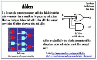
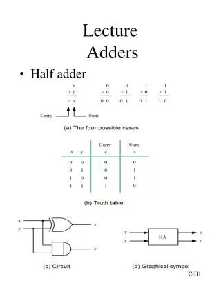
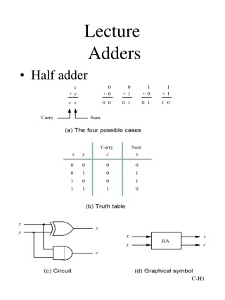
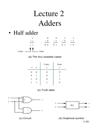
A Sum B Carry 1-bit Half Adder • Let’s first consider how to implement an 1-bit adder • Half adder • 2 inputs: A and B • 2 outputs: S (Sum) and Cout (Carry) 0 0 1 0 1 0 1 0
1-bit Full Adder • Half adder lacks a Cin input to accept Cout of the previous column • Full adder • 3 inputs: A, B, Cin • 2 outputs: S, Cout 0 0 0 1 0 1 0 1 0 1 1 0 1 0 1 1
1-bit Full Adder AB Cin Sum AB AB Cin Cin Cout or Slide from Prof. Sean Lee, Georgia Tech
A S B Cin Cout 1-bit Full Adder Schematic Half Adder Half Adder Slide from Prof. Sean Lee, Georgia Tech
Multi-bit Adder • It seems that an 1-bit adder is doing not much of work • Let’s move on to a multi-bit adder • N-bit adder sums two N-bit inputs (A and B), and Cin (carry-in) • It is commonly called carry propagate adders (CPAs) because the carry-out of one bit propagates into the next bit • Three common CPA implementations • Ripple-carry adders (slow) • Carry-lookahead adders (fast) • Prefix adders (faster)
Ripple-Carry Adder • The simplest way to build an N-bit CPA is to chain 1-bit adders together • Carry ripples through entire chain Example: 32-bit Ripple Carry Adder
A3 B3 A2 B2 A1 B1 A A A A B B B B Full Adder Full Adder Full Adder Full Adder Cin Cin Cin Cin Cout Cout Cout Cout Carry S S S S S3 S2 S1 4-bit Ripple-Carry Adder A0 B0 S0 S0 A B S Cin Cout Modified from Prof Sean Lee’s Slide, Georgia Tech
Delay of Ripple Carry Adder A0 B0 Carry Cin S0 1st Stage Critical Path = 3 gate delays = DXOR+DAND+DOR Slide from Prof. Sean Lee, Georgia Tech
A1 B1 S1 Delay of Ripple Carry Adder A0 B0 Cin S0 2nd Stage Critical Path = 2 gate delays = DAND+DOR (Assume that inputs are applied at the same time) 1st Stage Critical Path = 3 gate delays = DXOR+DAND+DOR Slide from Prof. Sean Lee, Georgia Tech
Delay of Ripple Carry Adder A3 B3 A2 B2 A1 B1 A0 B0 Carry Cin S3 S2 S1 S0 • Critical path delay of a 4-bit ripple carry adder • DXOR + 4 (DAND+DOR) : 9 gates delay • Critical path delay of an N-bit ripple carry adder • 2(N-1)+3 = (2N+1) gate delays Modified from Prof Sean Lee’s Slide, Georgia Tech
Ripple-Carry Adder Delay • Ripple-carry adder has disadvantage of being slow when N is large • The delay of an N-bit ripple-carry adder is roughly tripple = N • tFA (tFA is the delay of a full adder) • A faster adder needs to address the serial propagation of the carry bit
Carry-Lookahead Adder • The fundamental reason that large ripple-carry adders are slow is that the carry signals must propagate through every bit in the adder • A carry-lookahead adder (CLA) is another type of CPA that solves this problem. • It divides the adder into blocks and provides circuitry to quickly determine the carry-out of a block as soon as the carry-in is known
Carry-Lookahead Adder • Compute the carry-out (Cout) for an N-bit block • Compute generate (G) and propagate (P) signals for columns and then an N-bit block • A column (bit i) can produce a carry-out by either generating a carry-out or propagating a carry-in to the carry-out • Generate (Gi) and Propagate (Pi) signals for each column • A column will generate a carry-out if both Aiand Bi are 1 Gi = Ai Bi • A column will propagate a carry-in to the carry-out if either Aior Bi is 1 Pi = Ai + Bi • Express the carry-out of a column (Ci) in terms of Pi and Gi Ci = Ai Bi + (Ai + Bi )Ci-1 = Gi + Pi Ci-1
Carry Generate & Propagate gi = Ai Bi pi = Ai + Bi Ci = AiBi + (Ai + Bi) Ci-1 Ci = gi + pi Ci-1 C0 = g0 + p0 C-1 C1 = g1 + p1 C0 = g1 + p1 g0 + p1 p0C-1 C2 = g2 + p2C1 = g2 + p2 g1 + p2 p1 g0 + p2 p1 p0C-1 C3 = g3 + p3 C2 = g3 + p3 g2 + p3 p2 g1 + p3 p2 p1 g0 + p3 p2 p1 p0C-1 What do these equations mean? Let’s think about these equations for a moment Modified from Prof H.H.Lee’s Slide, Georgia Tech
Carry Generate & Propagate • A 4-bit block will generate a carry-out if column 3 generates (g3) a carry or if column 3 propagates (p3) a carry that was generated or propagated in a previous column G3:0 =g3+ p3 (g2+ p2 (g1+ p1 g0) = g3 + p3 g2 + p3 p2 g1 + p3 p2 p1 g0 • A 4-bit block will propagate a carry-in to the carry-out if all of the columns propagate the carry P3:0 = p3 p2 p1 p0 • We compute the carry-out of the 4-bit block (Ci) as Ci = Gi:j + Pi:jCj-1
C3 C-1 C1 C0 C2 g1 g3 g2 p1 p3 p2 g0 p0 A2 A1 A3 B1 B3 B2 A0 B0 S2 S1 S3 S0 4-bit CLA Carry Lookahead Logic Slide from Prof. Sean Lee, Georgia Tech
C3 g3 p3 g2 p2 g1 p1 g0 p0 C2 C1 C0 An Implementation of CLA C-1 S3 A3 B3 S2 A2 B2 S1 A1 B1 S0 A0 B0 C0 = g0 + p0 C-1 C1 = g1 + p1 C0 = g1 + p1 g0 + p1p0 C-1 C2 = g2 + p2 C1 = g2 + p2 g1 + p2p1 g0 + p2 p1p0 C-1 C3 = g3 + p3 C2 = g3 + p3 g2 + p3p2 g1 + p3p2 p1 g0 + p3 p2 p1p0 C-1 • Carry Delay is 4*DAND + 2*DOR for Carry C3 • Reuse some gate output results in little Improvement Slide from Prof. Sean Lee, Georgia Tech
g3 p3 C2 g2 p2 C1 g1 p1 C0 g0 p0 More Expensive and Fast CLA Carry Lookahead Logic C-1 C3 S3 A3 B3 S2 A2 B2 S1 A1 B1 S0 A0 B0 C0 = g0 + p0 C-1 C1 = g1 + p1 C0 = g1 + p1 g0 + p1p0 C-1 C2 = g2 + p2 C1 = g2 + p2 g1 + p2p1 g0 + p2 p1p0 C-1 C3 = g3 + p3 C2 = g3 + p3 g2 + p3p2 g1 + p3p2 p1 g0 + p3 p2 p1p0 C-1 Only 3 Gate Delay for each Carry Ci = DAND + 2*DOR Slide from Prof. Sean Lee, Georgia Tech
32-bit CLA with 4-bit blocks C0 = g0 + p0 C-1 C1 = g1 + p1 C0 = g1 + p1 g0 + p1 p0C-1 C2 = g2 + p2C1 = g2 + p2 g1 + p2 p1 g0 + p2 p1 p0C-1 C3 = g3 + p3 C2 = g3 + p3 g2 + p3p2 g1 + p3p2 p1 g0 + p3 p2 p1p0 C-1 C3 = g3 + p3 C2 = g3 + p3(g2 + p2C1) = g3 + p3(g2 + p2 (g1 + p1 C0)) = g3 + p3(g2 + p2 (g1 + p1( g0 + p0 C-1))) It shows a path to C3 only
CLA Delay • The delay of an N-bit CLA with k-bit blocks is roughly: tCLA = tpg + tpg_block+ (N/k – 1)tAND_OR + ktFA where • tpg is the delay of the column generate and propagate gates • tpg_block is the delay of the block generate and propagate gates • tAND_OR is the delay from Cin to Cout of the final AND/OR gate tpg tpg_block tAND_OR
Adder Delay Comparisons • Compare the delay of 32-bit ripple-carry adder and CLA • The CLA has 4-bit blocks • Assume that each two-input gate delay is 100 ps • Assume that a full adder delay is 300 ps tripple = NtFA = 32(300 ps) = 9.6 ns tCLA = tpg + tpg_block + (N/k – 1)tAND_OR + ktFA = [100 + 600+ (7)200 + 4(300)] ps = 3.3 ns
Verilog-HDL Representation module adder #(parameter N = 8) (input [N-1:0] a, b, input cin, output [N-1:0] s, output cout); assign {cout, s} = a + b + cin; endmodule
Then, When to Use What? • We have discussed 3 kinds of CPA • Ripple-carry adder • Carry-lookahead adder • Prefix adder (see backup slides) • Faster adders require more hardware and therefore they are more expensive and power-hungry • So, depending on your speed requirement, you can choose the right one • If you use HDL to describe an adder, the CAD tools will generate appropriate logic considering your speed requirement
Prefix Adder • Computes generate and propagate signals for all of the columns (!) to perform addition even faster • Computes G and P for 2-bit blocks, then 4-bit blocks, then 8-bit blocks, etc. until the generate and propagate signals are known for each column • Then, the prefix adder has log2N stages • The strategy is to compute the carry in (Ci-1) for each of the columns as fast as possible and then to compute the sum: Si = (AiÅ Bi)Å Ci-1
Prefix Adder • A carry is generated by being either generated in a column or propagated from a previous column • Define column -1 to hold Cin, so G-1 = Cin, P-1 = 0 Then, Ci-1 = Gi-1:-1 because there will be a carry out of column i-1 if the block spanning columns i-1 through -1 generates a carry • Thus, we can rewrite the sum equation as: Si = (AiÅ Bi)Å Gi-1:-1
Prefix Adder • The generate and propagate signals for a block spanning bits i:j are Gi:j = Gi:k+ Pi:k Gk-1:j Pi:j = Pi:kPk-1:j • These signals are called the prefixes because they must be precomputed before the final sum computation can complete • In words, these prefixes describe that • A block will generatea carry if the upper part (i:k) generates a carry or the upper part propagates a carry generated in the lower part (k-1:j) • A block will propagate a carry if both the upper and lower parts propagate the carry.
4-bit Prefix Adder Remember that P2:-1 is always “0” since P-1 = 0, but intermediate propagate signals (P1:-1 ,P0:-1 ,P2:1) are used for calculating subsequent generate signals A3 A2 A1 A0 Cin B3 B2 B1 B0 + + + + + + + + G-1 = Cin, P-1 = 0 P2, G2 P1, G1 P0, G0 P-1, G-1 Pi = Ai Bi , Gi = Ai + Bi P2:1, G2:1 P0:-1, G0:-1 P2:1 = P2 P1, G2:1 = G2 + P2 G1 P0:-1 = P0 P-1, G0:-1 = G0 + P0 G-1 P1:-1 = P1 P0:-1 , G1:-1 = G1 + P1 G0:-1 P2:-1 = P2:1 P0:-1 , G2:-1 = G2:1 + P2:1 G0:-1 P2:-1, G2:-1 P1:-1, G1:-1 S3 = A3 B3 G2:-1 S2 = A2 B2 G1:-1 S1 = A1 B1 G0:-1 S0 = A0 B0 G-1 C2 = G 2:-1 C1 = G 1:-1 C0 = G 0:-1 C-1 = G -1 S3 S2 S1 S0
16-bit Prefix Adder G-1 = Cin, P-1 = 0
Prefix Adder Delay • The delay of an N-bit prefix adder is: tPA = tpg + log2N(tpg_prefix ) + tXOR where • tpg is the delay of the column generate and propagate gates • tpg_prefix is the delay of the black prefix cell