Adders
Adders. Binary Adders. Arithmetic circuit Addition Subtraction Division Multiplication. 0 + 0 = 0 0 + 1 = 1 1 + 0 = 1 1 + 1 = 10. One bit in sum. Two bit in sum. Half Adder. A combinational circuit that performs the addition of two bits. Two inputs and two outputs.


Adders
E N D
Presentation Transcript
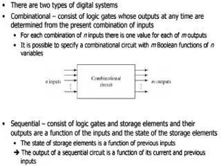
Binary Adders • Arithmetic circuit • Addition • Subtraction • Division • Multiplication
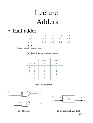
0 + 0 = 0 • 0 + 1 = 1 • 1 + 0 = 1 • 1 + 1 = 10 One bit in sum Two bit in sum
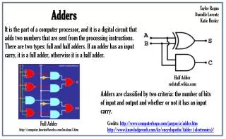
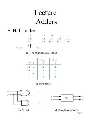
Half Adder • A combinational circuit that performs the addition of two bits. • Two inputs and two outputs. • Augend and Addend • Sum and Carry
Full Adder • A combinational circuit that performs the addition of three input bits. • Three inputs and two outputs. • Sum and Carry
Binary Ripple Carry Adder • Adders connected in cascade. • Carry output from one full adder connected to carry input of next full adder.
Input carry 0110 • A 1011 • B 0011 • Sum 1110 • Output carry 0011
Input carry in the least significant position is 0. • Simple in concept. • Long circuit delay. • Many gates in the carry path.
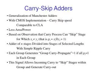
Why a Carry Lookahead Adder? • Practical design with reduced delay. • For a n- bit ripple carry adder • The longest delay path is 2n + 2. • 16 – bit ripple carry adder - delay is 34 gate delays
Carry Lookahead Adder • Designed by a transformation of the ripple carry adder design in which the carry logic over fixed groups of bits of the adder is reduced to two-level logic.
Design • OR gate and one of the AND gates are removed to form each of the full adders to form the ripple carry adder. • Separate the parts of full adders not involving the carry propagation path from those containing the path. • First part of each full adder • partial full adder - PFA
Two outputs • Pi and Gi • From each PFA to ripple carry path • One input • Ci • From the carry path to each PFA
Pi = Ai XOR Bi - Propagate function • Gi = Ai . Bi - Generate function
WheneverPi = 1 • Incoming carry is propagated through bit position from Ci+1. • WheneverPi = 0 • carry propagation through bit position is blocked.
WheneverGi = 1 • Carry output from the position is 1. • Regardless of value of Pi. • A Carry has been generated. • WheneverGi = 0 • carry is not generated. • Ci+1 is 0. • Ci is also 0.
Generate and propagate functions correspond exactly to the half adder. • Essential in controling the values in ripple carry path. • PFA generates sum function by XOR of incoming carry, Ciand propagate function, Pi.