Analysis of Coupled Transmission Lines with Differential and Common Mode Operations
This document presents a comprehensive analysis of coupled transmission lines, focusing on both common and differential mode behavior. It examines parameters such as voltage, equivalent resistance, and signal propagation times. The study provides insight into the voltage relationships and equivalent circuit modeling for line terminations at specific resistances (e.g., 50Ω and 250Ω). It includes calculations for forward and backward waves, as well as the effect of matched termination on signal integrity. The findings are relevant for optimizing high-frequency circuit designs.

Analysis of Coupled Transmission Lines with Differential and Common Mode Operations
E N D
Presentation Transcript
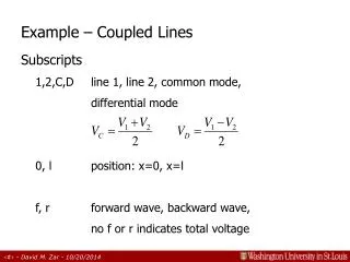
Example – Coupled Lines Subscripts 1,2,C,D line 1, line 2, common mode, differential mode 0, l position: x=0, x=l f, r forward wave, backward wave, no f or r indicates total voltage
+ – 1 V 0 V 0ns 1ns Coupled Lines V1l V2l (Rx is the equivalent R in the terminated case) R1 = 50Ω 50Ω 50Ω R2 = 250Ω V10 V20 l/vD = 5ns 50Ω l/vC = 4.5ns
250 V10 V20 + – 50 50 50 0ns 1ns t = 0+ x = 0 1 V 0 V V10 1/11 V 0 V V20=25/275V Equivalent Z Model Line 2 Rs 0ns 1ns 6/11 V 0 V Remember: Vc = (V1+V2)/2 Vd = (V1-V2)/2 5/11 V 0 V
t = l/v+ x = l 250 V1l V2l + - 50 50 50 50 + – + – 2·VClf 2·VClf Line 1 Rt Line 2 Rt 4ns 4.5ns 5ns 5.5ns 6ns 6/11 V 0 V VClf 5/11 V 0 V VDlf
4ns 4.5ns 5ns 5.5ns 6ns 6/11 V VCl 0 V (7/6)·(5/11) V 0 V VDl (6/11)+(35/66) = 71/66 V V1l 3/11 V V2l 3/11 V + (1/66)
250 If matched termination t = l/v+ x = l VDlf·2·7 250 + - 50 50 50 50 + – + – 2·VClf 4ns 4.5ns 5ns 5.5ns 6ns 6/11 V VClf 5/11 V VDlf 1 V V1l 3/11 V V2l 1/11 V