Download
1 / 13
130 likes | 240 Views
This document outlines the progress of a sophisticated control system for managing very high voltage (VHV) supplies, specifically designed for TPC applications. The system incorporates a 100 kV power supply featuring precise ramp-up and ramp-down capabilities, real-time power monitoring, and safety mechanisms to respond to cooling or gas system failures. Customized for TPC needs, the solution includes robust PLC and external interlock configurations, ensuring reliability and insensitivity to noise. The integration of RS-232 communication interfaces further enhances operational efficiency.

E N D
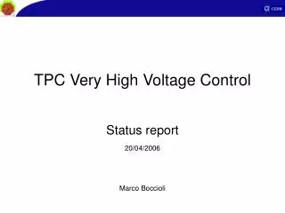
TPC Very High Voltage Control Detector system progress Marco Boccioli
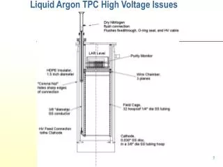
TPC VHV Supply • TPC electric field cage • 100 kV in the central electrode
The system • Power supply control • Ramp up, ramp down • Power monitoring • Monitoring of currents in field cage • Safety monitoring • Intervention in case of cooling or gas system failure
TPC VHV Supplier Heinzinger PNC 150000 • 150 kV • 0.001% ripple • Remotely controllable via RS-232 • Customized for TPC needs (limited ramp speed)
Power Supply Control 100 kV Ramping up • Short ramps followed by a check pause • After 50kV, longer check pauses (double) • Total ramping time: 21’ 20’’ (200 V/s)
V Rmoni R167 R1 R2 R3 R4 100 kV Central electrode Power monitoring • Resistor rod current monitored as voltage drop over the last element Rmoni • Failure in one rod resistor produces a voltage drop
“ DCS ” PC/PVSS RS232 CAN ELMB power ELMB External interlocks R RS232 Dig. I/O Heinzinger power supply CR4 UX L3 ELMB ELMB 1.5V 1.5V - - 0 0 TPC VHV Supply Control Different solutions were considered A: PC / ELMB B: PLC C: PLC / ELMB PC control: not robust enough Hardware updates ELMB: noise insensitive
CR4 UX L3 “ DCS ” . Ethern bus PLC RS232 Dig. I/O External interlocks R RS232 Dig. I/O Heinzinger power supply PLC bus Remote I/O An. Inp 1.5V 1.5V - - 0 0 TPC VHV Supply Control A: PC / ELMB B: PLC C: PLC / ELMB PLC remote I/O: noise sensitive Difficult to make interlocks raise Reset PLC: Reliability
CR4 UX L3 TPC VHV Supply Control “DCS” A: PC / ELMB B: PLC C: PLC / ELMB . PLC Ethern CAN ELMB power RS232 Dig. I/O External interlocks R Dig. I/O RS232 Heinzinger ELMB: noise insensitive PLC: reliability power supply ELMB ELMB 1.5V 1.5V - - 0 0
The Implementation (1) Chosen configuration: C • PLC more reliable than a PC • Better timing for ramping • Components long-term availability • PLC can compute external interlocks • Interlock dependent reaction time • ELMB can be placed close to the experiment • Avoid of cable interference
The Implementation (2) • PLC: Schneider Electric Premium • Ethernet + 2 communication protocols • RS-232 interface PLC module • CAN bus interface PLC module
interlocks Rack CR4-Z08 TPC cage PLC Wiring, I/O “DCS” RS 232 CAN Ether net 1m Power S. 13 digital inputs 6 digital inputs 1 digital output ELMB power 100m ELMB 2m ELMB 12 analog inputs 0~1.5 V
Situation • Configuring system prototype • PS being modified by Heinzinger • Implementing PLC control routines • Main routine • RS-232 communication • CAN bus communication