Download
1 / 21
230 likes | 396 Views
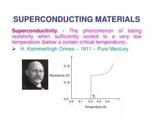
Superconducting Materials R&D : RRCAT-JLAB Collaboration. S B Roy Materials & Advanced Accelerator Science Division RRCAT, Indore. Collaborators: M. K. Chattopadhyay , V. C. Sahni , G. R. Myneni , P Prakash. Superconducting Materials R&D : Overall Aim

E N D
Superconducting Materials R&D: RRCAT-JLAB Collaboration S B Roy Materials & Advanced Accelerator Science Division RRCAT, Indore Collaborators: M. K. Chattopadhyay, V. C. Sahni, G. R. Myneni , P Prakash
Superconducting Materials R&D : Overall Aim • Tuning superconducting properties of a suitable material for fabrication of an energy efficient and cost effective SC-RF accelerator structure. • Achieving reliability and reproducibility in the SC-RF cavity performance. • Gain knowledge and experience to venture into newer energy efficient and superior materials.
Superconducting Radio Frequency (SCRF) Cavity ‘An RF power source’ fills the RF cavity via a ‘coupler’. EM field will accelerate & impart energy to the charge particles if they are in phase with the electric field.
What do we want from a good cavity ? High Quality Factor:Q = (Stored energy)/(Dissipated power) As high a gradient as possible Dissipated power: For copper at 300 K 1.3 GHz, Rs Copper= 9.4 mΩ For bulk Nb at 2K RBCS 10 n Superconducting RF cavities excel in applications where one needs ‘continuous wave or long-pulse’ acceleration with gradients above a few million volts per meter (MV m-1)
Materials and surface issues in Niobium SCRF cavities: Extrinsic effects • Surface roughness, grain boundaries Electrical break down; ↓Gradient • Impurities Depress superconductivity, increase Rresidual. • Surface Oxides Suspected to degraded SC response?? NO • Field emission and multipacting Quenching of the Cavity. Most of these problems are solved with proper cavity shape, and chemical treatment and cleaning of cavity surface. Field emission free cavities reaching up to 30-35 MV m-1 are obtained regularly in various labs. But Nb elliptical 1.3 GHz SCRF cavities at 2K are supposed to give 45 MV m-1?!
Two fundamental limits for a SC-RF cavity: (1) A critical rf magnetic field above which the perfect SC state is destroyed -- limits the Accelerating Field or Gardient. (2)The surface resistance as predicted by the microscopic BCS theory. -- limits Q.
Nb for SCRF cavity fabrication: Material qualifying criterion *Current approach mainly relies on improving the residual resistivity ratio (RRR) of the Nb. Involves expensive Niobium refinement process. *With high RRR Nb + right cavity shape + chemical treatment Extrinsic (+ surface) defects are low & so cavity loss reduces. *But high RRR does not necessarily say how good are the SC properties of Niobium & at best gives indirect information on thermal conductivity. *All cavities fabricated in the same way do not give high gradients. * Cavity gradient seldom reaches above 40 Mv m-1
Two Major Open Issues in RF Superconductivity of Niobium: (1) What is the RF critical magnetic field in Niobium? Is it • Thermodynamical critical field-Hc or field for first flux line penetration-HP? • How does it depend on temperature? (2) Why does the RF surface resistance of niobium increase sharply at high RF magnetic field? -- High-field slope in the quality factor-Q-slope HC1 Nb SCRF cavities working at 2K are supposed to give 45 MV m-1?!
SCRF Materials R&D HC1<H<HC2 => Abrikosov lattice or Vortex state => important for high critical current (Jc) applications e.g. SC magnets HHC1(T) => important for RF superconductivityapplications
Points we are examining (in Nb & other SC materials) Role of HP and how it may be varying with, (1)the methods of Nb materials preparation, grain size ? (2)the surface chemical treatment of Nb: Electropolishing versus BCP ? (3)thermal treatment -- annealing temperature and time ? Through an understanding of the microscopic properties of the materials treated differently we can possibly identify SC materials, which will give best performance. A better qualification scheme is needed using HC1 or Hp and RSsince thoseset limits on achievable SC-RF accelerating gradients.
MagnetizationMeasurements The basic VSM measurement is accomplished by oscillating the sample near a detection(pickup) coil and synchronously detecting the voltage induced. By using a compact gradiometer pickup coil configuration, a relatively large oscillation amplitude (1-3mm peak) and a frequency of 40 Hz, the system is able to resolve Magnetization changes of less than 10-6 emu at a data rate of 1 Hz. The sample is attached to the end of a sample rod that is driven sinusoidally. The center of oscillation is positioned at the vertical center of a gradiometer pickup coil. The voltage induced in the pickup coil is amplified and lock-in detected in the VSM detection module.
Effect of BCP treatment on Nb samples Nb samples obtained from the same batch that was used for makingSCRF cavities at JLab, USA, subjected to same BCP and annealing treatmentsas was given to the SCRF cavities. EstimatedHC1 (or Hp) of the BCP treated samplescorrelates well with the reportedsurface magnetic fieldsabove which a severe degradation of theQ-factoris observed in theBCP treated Nb SC-RF cavities.
Effect of BCP treatment on the TC of Nb samples Samples from Jlab, USA. Conclusions BCP degrades SC properties, Tc, HC1 and HC2 , significantly, hence not quite desirable.
Main results in a nutshell → BCP treatment lowers the field at which magnetic flux lines enter the material as compared to that in pristine Nb. RF cavity prepared with such BCP Nb would reach maximum 30-32 MV/m
Effect of EP treatment on Nb samples Samples from IUAC, New Delhi
Effect of EP treatment on Nb samples Samples from IUAC, New Delhi Conclusion: Effect of EP treatment on SC properties of Nb is rather small. EP treatment is therefore preferable for processing Nb-SCRF cavities.
Effect of Ta impurities on the SC properties of Nb Samples from JLab Conclusions Higher Ta impurity only marginally affects SC properties. One can possibly use less pure materials to make cavities. Will reduce the cost of Nb refinement. –“By now there exists compelling evidence that the BCP process limits the attainable accelerating fields of multicell cavities to about 30 MV/m even if niobium of excellent thermal conductivity is used.” L. Lilje et al (DESY) arXiv Physics:0401134v1
Ongoing and future works : Fundamental physics & newer SCRF materials: • Which one is most influential:HC1or HP ? • Does upper critical field HC2 (or HC3) play any role in the SCRF cavity ? • Thermal instability in superconducting properties of Nb • – flux jump in Nb → role of thermal conductivity • Detailed study of surface resistance of superconductors RBCS in applied magnetic fields. • Nb thin films Nb-coated Copper cavities. • Newer materials : MgB2 ,Nb-Zr, Nb-Al, Mo-Re alloys etc.
Singlecrystal Nb Large grain Nb