Basic Logic Gates and De Morgan's Theorem
300 likes | 610 Views
Basic Logic Gates and De Morgan's Theorem. Discussion D5.1 Appendix D. Basic Logic Gates and Basic Digital Design. NOT, AND, and OR Gates NAND and NOR Gates XOR and XNOR Gates DeMorgan’s Theorem. NOT Gate -- Inverter. Y. X. 0 1. 1 0. Behavior:

Basic Logic Gates and De Morgan's Theorem
E N D
Presentation Transcript
Basic Logic Gatesand De Morgan's Theorem Discussion D5.1 Appendix D
Basic Logic Gates and Basic Digital Design • NOT, AND, and OR Gates • NAND and NOR Gates • XOR and XNOR Gates • DeMorgan’s Theorem
NOT Gate -- Inverter Y X 0 1 1 0 Behavior: The output of a NOT gate is the inverse (one’s complement) of the input
NOT • Y = ~X (Verilog) • Y = !X (ABEL) • Y = not X (VHDL) • Y = X’ • Y = X • Y = X (textook) • not(Y,X) (Verilog)
NOT X ~X ~~X = X X ~X ~~X 0 1 0 1 0 1
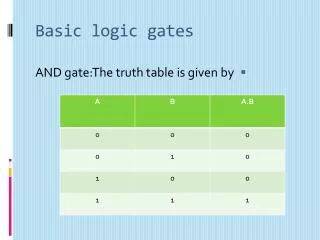
AND Gate AND X Y Z 0 0 0 0 1 0 1 0 0 1 1 1 X Z Y Z = X & Y
AND • X & Y (Verilog and ABEL) • X and Y (VHDL) • X Y • X Y • X * Y • XY (textbook) • and(Z,X,Y) (Verilog) V U
OR Gate OR X Y Z 0 0 0 0 1 1 1 0 1 1 1 1 X Z Y Z = X | Y
OR • X | Y (Verilog) • X # Y (ABEL) • X or Y (VHDL) • X + Y (textbook) • X V Y • X U Y • or(Z,X,Y) (Verilog)
Y X 0 1 1 0 Summary of Basic Gates Y = ~X not(Y,X) X Y NOT X Y Z 0 0 0 0 1 0 1 0 0 1 1 1 Z = X & Y and(Z,X,Y) X AND Z Y X Y Z 0 0 0 0 1 1 1 0 1 1 1 1 Z = X | Y or(Z,X,Y) X OR Z Y Any logic circuit can be created using only these three gates
Basic Logic Gates and Basic Digital Design • NOT, AND, and OR Gates • NAND and NOR Gates • XOR and XNOR Gates • DeMorgan’s Theorem
NAND Gate NAND X Y Z 0 0 1 0 1 1 1 0 1 1 1 0 X Z Y Z = ~(X & Y) nand(Z,X,Y)
NAND Gate NOT-AND X Y W Z 0 0 0 1 0 1 0 1 1 0 0 1 1 1 1 0 X W Z Y W = X & Y Z = ~W = ~(X & Y)
2-Input NAND Gate NAND X Y Z 0 0 1 0 1 1 1 0 1 1 1 0 X Z Y Z = ~(X & Y) nand(Z,X,Y)
NOR Gate NOR X Y Z 0 0 1 0 1 0 1 0 0 1 1 0 X Z Y Z = ~(X | Y) nor(Z,X,Y)
NOR Gate NOT-OR X Y W Z 0 0 0 1 0 1 1 0 1 0 1 0 1 1 1 0 X W Z Y W = X | Y Z = ~W = ~(X | Y)
2 Input NOR Gate NOR X Y Z 0 0 1 0 1 0 1 0 0 1 1 0 X Z Y Z = ~(X | Y) nor(Z,X,Y)
Basic Logic Gates and Basic Digital Design • NOT, AND, and OR Gates • NAND and NOR Gates • XOR and XNOR Gates • DeMorgan’s Theorem
Exclusive-OR Gate XOR X Y Z X Z 0 0 0 Y 0 1 1 Z = X ^ Y xor(Z,X,Y) 1 0 1 1 1 0
XOR • X ^ Y (Verilog) • X $ Y (ABEL) • X @ Y • xor(Z,X,Y) (Verilog)
X Z Y 2-Input XOR Gate XOR X Y Z 0 0 0 0 1 1 1 0 1 1 1 0 Z = X ^ Y xor(Z,X,Y) Note: if Y = 0, Z = X if Y = 1, Z = ~X Therefore, an XOR gate can be used as a controlled inverter
Exclusive-NOR Gate XNOR X Y Z X Z 0 0 1 Y 0 1 0 Z = ~(X ^ Y) Z = X ~^ Y xnor(Z,X,Y) 1 0 0 1 1 1
XNOR • X ~^ Y (Verilog) • !(X $ Y) (ABEL) • X @ Y • xnor(Z,X,Y) (Verilog)
2-Input XNOR Gate XNOR X Y Z 0 0 1 0 1 0 1 0 0 1 1 1 X Z Y Z = ~(X ^ Y) Z = X ~^ Y xnor(Z,X,Y) Note: Z = 1 if X = Y Therefore, an XNOR gate can be used as an equality detector
Basic Logic Gates and Basic Digital Design • NOT, AND, and OR Gates • NAND and NOR Gates • XOR and XNOR Gates • DeMorgan’s Theorem
NAND Gate X Z X Z = Y Y Z = ~(X & Y) Z = ~X | ~Y X Y W Z 0 0 0 1 0 1 0 1 1 0 0 1 1 1 1 0 X Y ~X ~Y Z 0 0 1 1 1 0 1 1 0 1 1 0 0 1 1 1 1 0 0 0
De Morgan’s Theorem-1 ~(X & Y) = ~X | ~Y • NOT all variables • Change & to | and | to & • NOT the result
NOR Gate X X Z Z Y Y Z = ~(X | Y) Z = ~X & ~Y X Y Z 0 0 1 0 1 0 1 0 0 1 1 0 X Y ~X ~Y Z 0 0 1 1 1 0 1 1 0 0 1 0 0 1 0 1 1 0 0 0
De Morgan’s Theorem-2 ~(X | Y) = ~X & ~Y • NOT all variables • Change & to | and | to & • NOT the result
De Morgan’s Theorem • NOT all variables • Change & to | and | to & • NOT the result • -------------------------------------------- • ~X | ~Y = ~(~~X & ~~Y) = ~(X & Y) • ~(X & Y) = ~~(~X | ~Y) = ~X | ~Y • ~X & ~Y = ~(~~X | ~~Y) = ~(X | Y) • ~(X | Y) = ~~(~X & ~Y) = ~X & ~Y