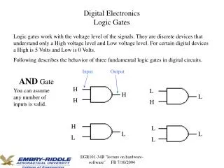
Basic Digital Logic Gates
Review of Digital Logic Design Concepts OR: What I Need to Know from Digital Logic Design (EEL3705). Basic Digital Logic Gates. A Review. Digital (Positive) Logic. Logic Level High 1 or ONE or HIGH or H or +Vdd or yes or ON or True Logic Level Low

Basic Digital Logic Gates
E N D
Presentation Transcript
Review of Digital Logic Design ConceptsOR: What I Need to Know from Digital Logic Design (EEL3705)
Basic Digital Logic Gates A Review
Digital (Positive) Logic • Logic Level High • 1 or ONE or HIGH or H or +Vdd or yes or ON or True • Logic Level Low • 0 or ZERO or LOW or L or GND or no or OFF or False 1 0
Definitions • Assert • A control signal is asserted when the action control by the signal is being done. • Ex: Assume a control signal labeled en • en is asserted when en is high • Active low signal • A signal that is asserted when it is a logic level low. • Active high signal • A signal that is asserted when it is a logic level high.
A Y Buffer or Driver Equation Symbol Truth Table
E A Y Tri-State Buffer or Driver Equation Symbol Truth Table Z = high impedance
NOT (Inverter) GATE Equation Symbol Truth Table
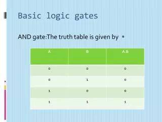
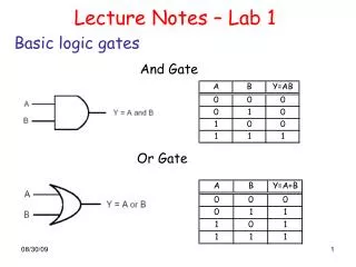
AND GATE Equation Symbol Truth Table
NAND GATE Equation Symbol Truth Table
OR GATE Equation Symbol Truth Table
NOR GATE Equation Symbol Truth Table
XOR GATE Equation Symbol Truth Table
XNOR GATE Equation Symbol Truth Table Equivalence Function
Digital Logic Types • Combinatorial Logic Circuits • No Memory (or Registers) • Sequential Logic Circuits • Memory (or Registers) • Asynchronous Logic Circuits • No common clock • Synchronous Logic Circuits • Common clock Synchronous Sequential Circuits
Memory Storage Registers Latches and Flip-Flops
D-Latch with (P)reset Symbol d = “don’t care” Equation (level clock) Truth Table • When Pre/SET (Preset) is asserted, Q → 1 immediately. • When Rst/CLR (Reset) is asserted, Q → 0 immediately. • When neither SET nor CLR is asserted, • Q → D (data) when E (enable) is asserted; • Maintains previous value otherwise.
D Flip-Flop Positive Edge Triggered Symbol Equation (rising clock) Truth Table • Q changes to D on rising edge of Clk
Basic Memory Devices • Registers • Basic • Multi-Function (Shift, Load, Hold, . . .) • Counters • Asynchronous • Synchronous • Up / Down • Modulo Counters
Finite State Machines (FSMs) • Three basic types • Moore FSM • Mealy FSM • Mealy-Moore FSM
Moore FSM General Block Diagram Next State Present State Output Vector Input Vector Clock Feedback Path Reset CL= Combinational Logic Cloud Reg= D Registers
Moore FSM State Equations Next State Present State Output Vector Input Vector Clock Feedback Path Reset State Equations
Mealy FSM State Equations Next State Present State Input Vector Output Vector Feedback Path
Mealy-Moore FSM State Equations Present State Next State Input Vector Mealy Outputs Moore Outputs
State Bubble Example Unconditional Transition State name = S0 State value = 00 Y = 0 for this state
Example 2– 2-bit Up Counter • State Diagram Clock is implied
Example – 2-bit Up Counter • State Table State Value Assignment Let Output Vector Let S0 = reset state
Example – 2-bit Up Counter • Truth Table
Example – 2-bit Up Counter • Excitation Equations
Recall Moore FSM Next State Present State Output Vector Input Vector Clock Feedback Path Reset State Equations
Reg Block F Logic Y Vector H Logic Logic Diagram No X Vector in this Example No H Logic needed
2-bit Counter in 68HC11 Assembly L0: LDAA #$00 ; Reset A with 0 L1: INCA ; A=A+1 CMPA #$03 ; Is A=3? BNE L1 ; No. Increment A JMP L0 ; Yes, Reset A to 0